# ENP-CAN
# CAN Bus Module
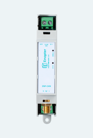
The CAN Bus Module is used to read data from devices such as vehicles, inverters, ventilation systems, valves, irradiance sensors, power meters and others. The CAN Bus Module sends the collected data to the Enapter Gateway and Cloud via secure wireless connection.
# Technical Data
| Parameter | Value |
|---|---|
| Voltage | 9…60 V DC |
| Wireless Communication | Wi-Fi 2.4 GHz Bluetooth 4.0 LE |
| Integrated connection type | CAN bus |
| Antenna connection type | SMA-F (module) – SMA-M (antenna) |
| Local signaling | 1 LED (green): steady – correct operation, blinking – establishing connection with server 1 LED (red): module error |
| Current consumption | 50 mA 12 V DC, max. 300 mA |
| Mounting | 35 mm Din rail acc. to IEC 60715 |
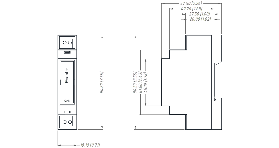
| Height | 90.2 mm (3.55 inch) |
| Depth | 57.5 mm (2.26 inch) |
| Width | 18.1 mm (0.71 inch) |
| Net weight | 0.050 kg |
# Environmental Conditions
| Parameter | Value |
|---|---|
| Ambient air temperature for operation | -40…+60 ℃ |
| Ambient air temperature for storage | -40…+60 ℃ |
| Relative humidity for operation | 20…90 %, without condensation |
| Relative humidity for storage | 20…90 %, without condensation |
| Operating altitude | 0…2000 m |
| Storage altitude | 0…3500 m |
| Pollution degree | 2 |
| IP degree of protection | IP20 |
# Connected device
| Parameter | Value |
|---|---|
| Type | Inverter Ventilation system Valve Irradiance sensor Power meter and others |
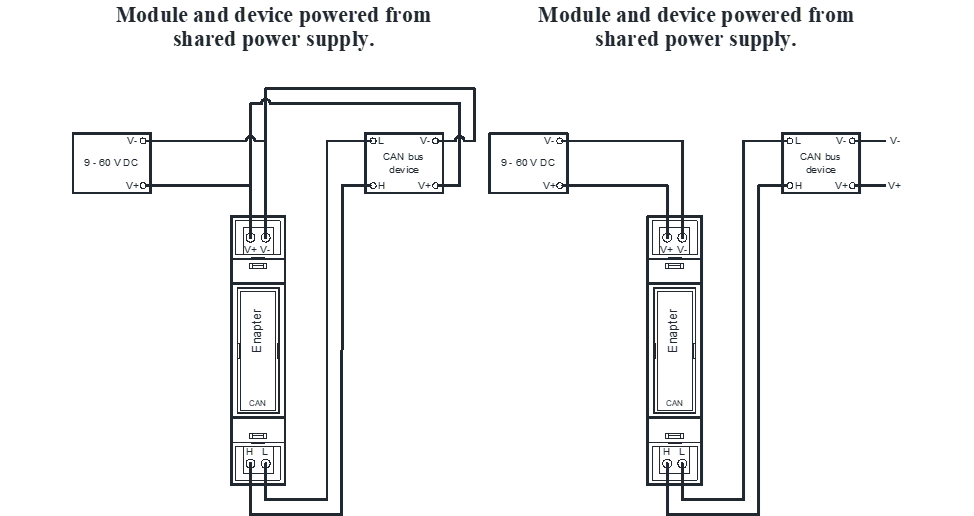
| Voltage supply | 9…60 V DC when module and device powered from shared power supply |
| Connection | 2-pin screw terminal block |
# Dimensions
The dimensions are in mm and in brackets in inch.
# Mounting
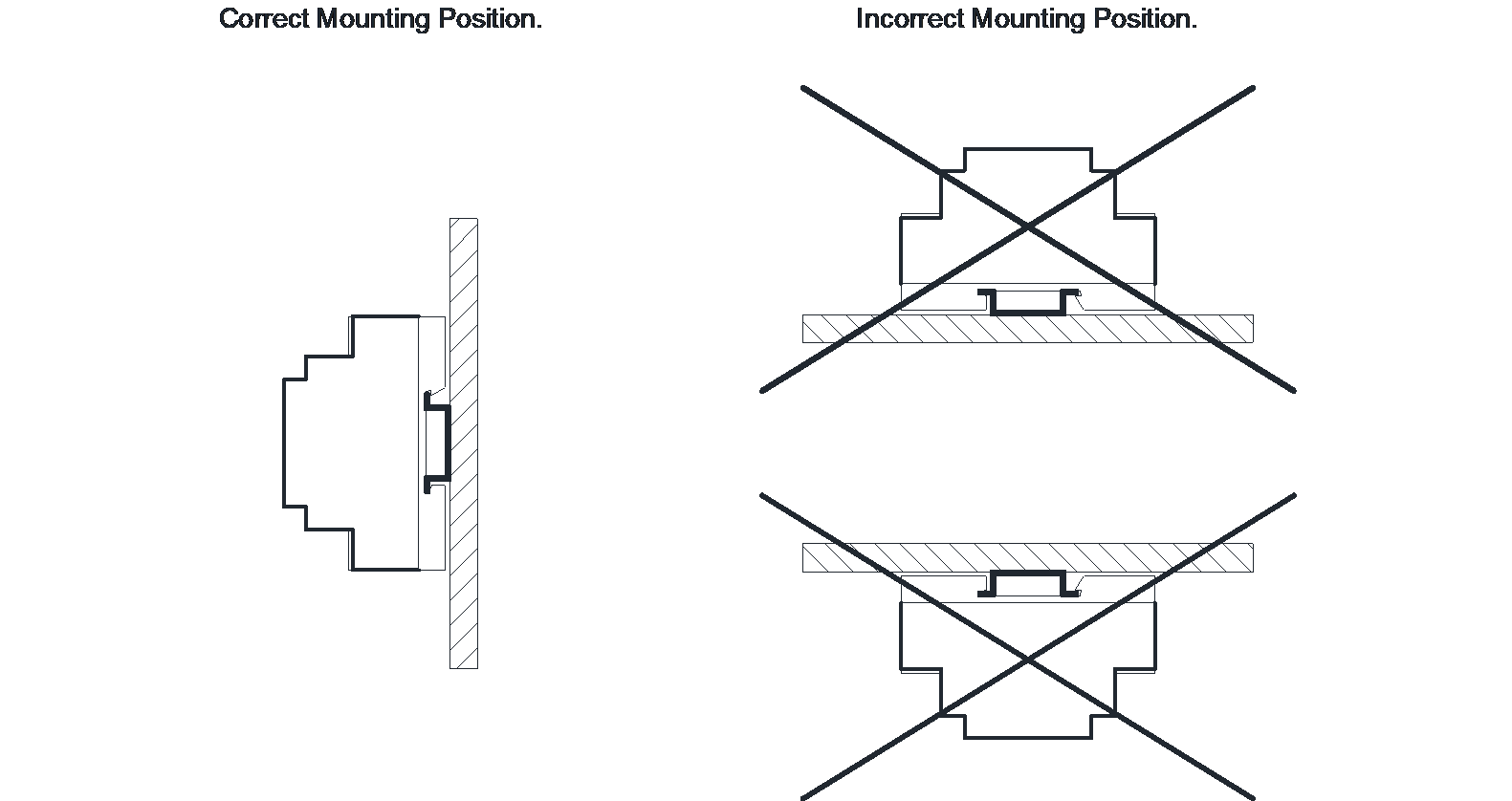
The ENP-CAN Module must be horizontally mounted on 35 mm DIN rail according to IEC 60715.
# Connection Examples
TIP
1 Amp Circuit Breaker recommended to use on power line for the ENP-CAN Module.
# Standards
Wi-Fi protocols – 802.11 b/g/n/e/i (802.11n up to 150 Mbit/s).
Bluetooth protocols – Bluetooth v4.2 BR/EDR and BLE specification.
# Warnings
WARNING
Alternating current voltage of 110 - 220 V is potentially lethal!
All works on assembly and installation should be performed only with a disconnected power supply!
The installation and assembly of electrical equipment must be carried out by electrically qualified persons.
The appearance of the product may differ from the images presented on the website or in this manual. The discrepancy between the appearance and packaging of the goods with a picture and description on the website or this manual is not an indication of poor quality goods. The manufacturer reserves the right to make changes to the design and packaging of the product without prior notice.
# Safety Instructions
Note
The installation and assembly of device must be carried out by electrician in accordance with the applicable regulations.
This device must be mounted on a DIN rail in an electrical distribution enclosure accordingly with this manual to ensure protection against contact, water and dust.
This device must not be used as part of safety-critical systems.
Edge processing scripting should be used as a convenience feature for basic non-realtime automation and not for life-sustaining or safety-critical use cases. Normal operation depend on working internet, Wi-Fi, and Enapter Cloud. Enapter is not responsible for any harms or losses incurred as a result of any failed automation.
# Lua API
Lua API lets to interact with 3rd party devices via our UCMs (opens new window). It includes functions that implement various kinds of interaction. For more information please visit Enapter Developer Toolkit (opens new window) and ENP-CAN Reference (opens new window).
# Troubleshooting
# The Module Is Not Receiving Telemetry
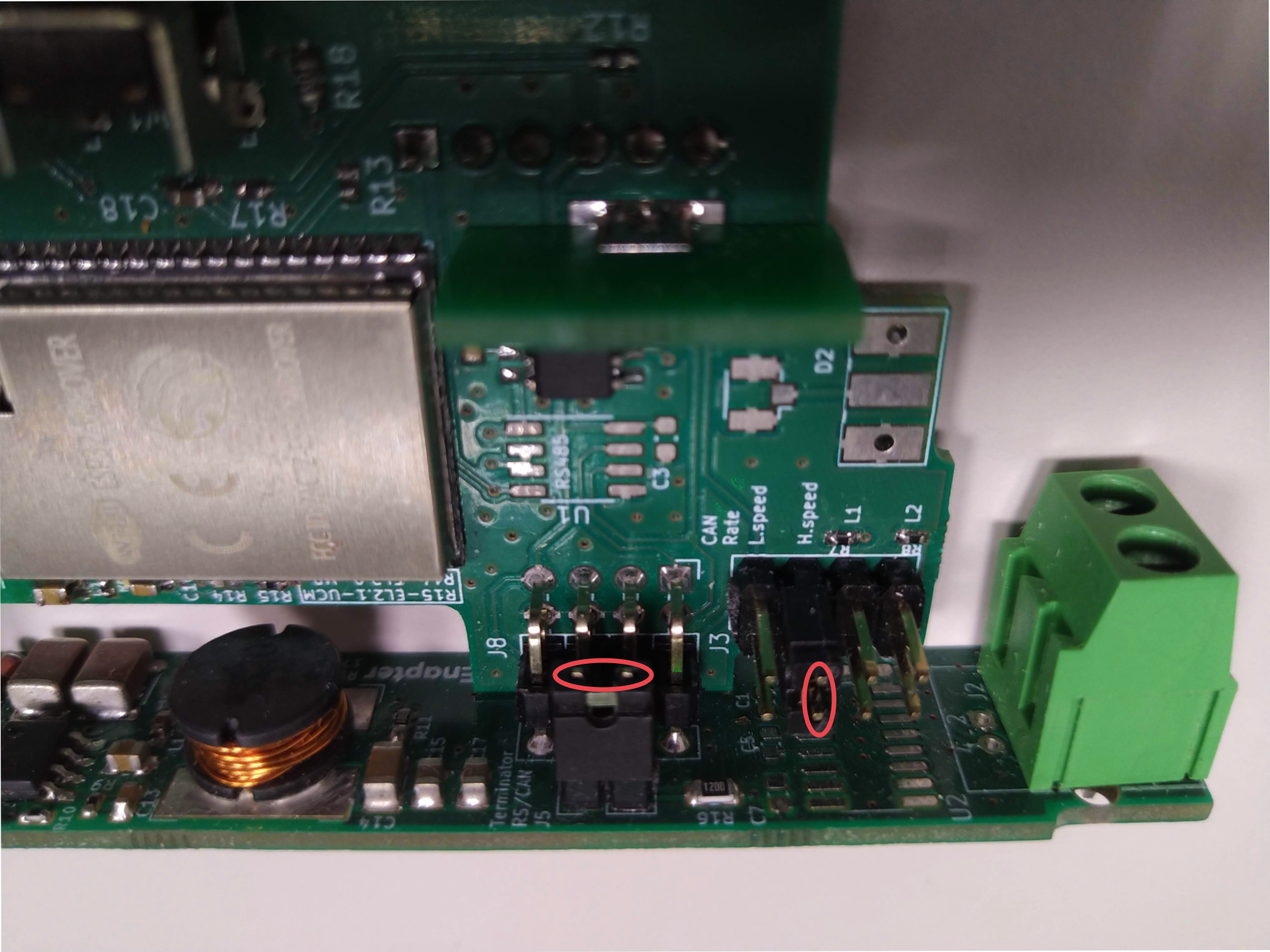
Check the jumpers inside the ENP-CAN module (install if needed):
- Dismount the antenna from the ENP-CAN module.
- Remove the front cover.
- Remove the back side of the module.
- Carefully push the module control board down.
- Install jumper J5, jumper J3 H.speed or both according to the picture below.
# Resources
ENP-CAN Module Quick Start Guide (EN)
ENP-CAN Module CAD Drawings (2D)
ENP-CAN Module CAD Drawings (3D DWG)
ENP-CAN Module CAD Drawings (3D STP)
# 💬 Need Help?
Have a question or hit a roadblock? Join the Enapter Discord community (opens in a new tab) to get quick support, exchange ideas, and collaborate with other developers and energy experts.
Was this page useful?
