# Gateway Software
- 🔥 What's New
- 🛠️ Features
- 📖 Downloads
- ✅ Required Equipment
- 🚀 Installation Guide
- ⚙️ Operational Modes
- ☁️ Cloud Mode
- 🏝️ Island Mode
- 🔧 Enapter Gateway Factory Reset
- 🌐 Virtual UCM
- 🛠️ Rule Engine
- 🖥️ Command Line Interface
- 🕸️ Public MQTT API
- 💻 OPC UA
- 🤖 Creating Enapter Rule (Automation)
- 💼 Enapter Rule Engine Use Cases
- 🧠 Updating Gateway Software
The Gateway is an energy site and IoT controller that optimizes energy systems operating either fully or partially off-grid. It manages energy storage, energy consumption, solar PV, and other generators, and performs islanding control during blackouts. Additionally, the gateway autonomously maintains data backup in case of an unstable internet connection and reduces traffic by leveraging telemetry compression.
# 🔥 What's New
- Gateway 2.5: security improvements
- Gateway 2.4: bug fixing, base system packages update, support for easy network pre-configuration.
- Gateway 2.3: the base OS is now based on the recently open-sourced layer of Enapter Linux.
- Gateway 2.2: industrial-grade hardware support and improved reliability.
- Gateway 2.1: Enapter devices auto-discovery, OPC UA and HTTP APIs, and Grafana plugin.
# 🛠️ Features
The gateway software provides the following functions:
- Internet connectivity issues mitigation for reliable data delivery to Enapter Cloud.
- Aggregated data from all devices such as UCMs and Electrolysers, and data compression.
- OPC UA and HTTP API interfaces for 3rd party integrations.
- Public MQTT for 3rd party integrations.
- Rule Engine for energy system automation with Lua scripts.
# 📖 Downloads
Note
The latest version of Gateway Software can be found at fw.enapter.com (opens new window).
# ✅ Required Equipment
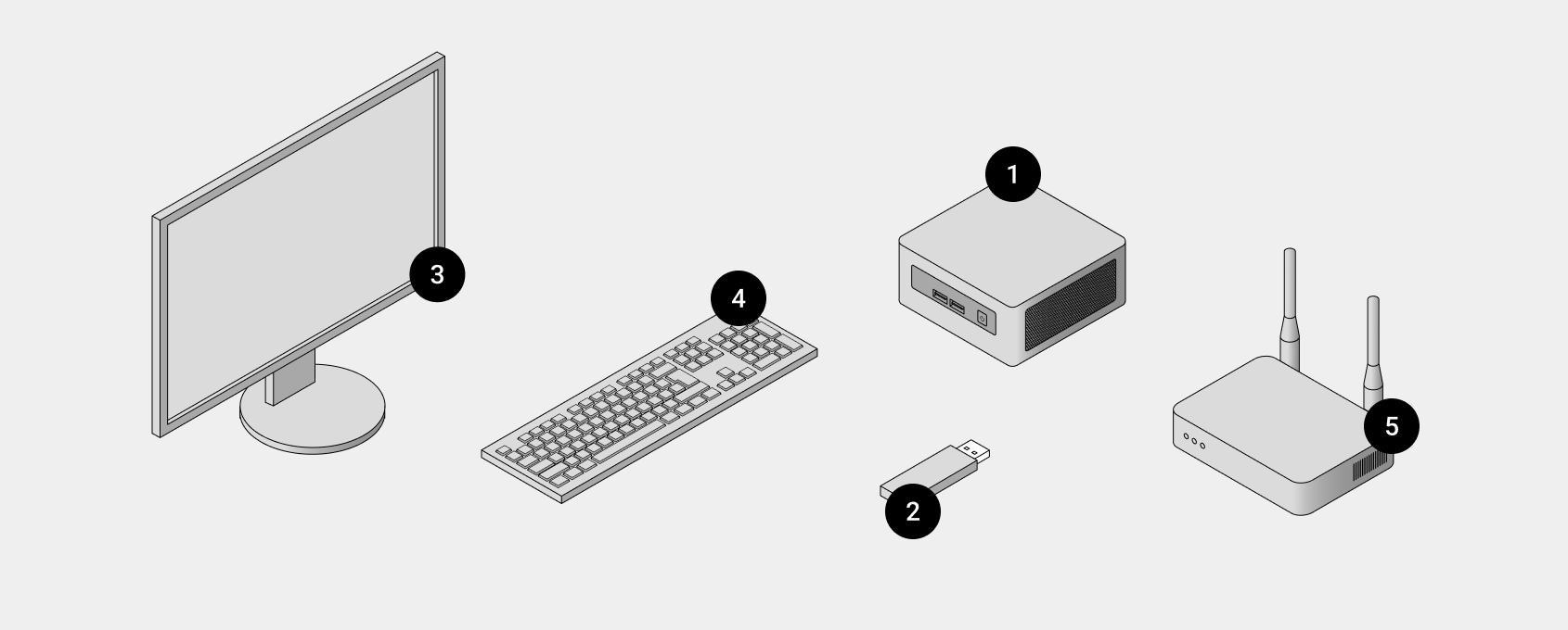
- Intel NUC computer with suitable power supply.
- USB flash drive 16 GB minimum.
- External Monitor with HDMI cable.
- USB Keyboard.
- Wi-Fi Router with Ethernet Cable.
# Purchase Intel NUC
The wide range of Intel NUC models is supported, though minimal system requirements are applicable.
| Recommended Configuration | Minimal Configuration | |
|---|---|---|
| NUC Model | Intel® NUC 10th generation or later | Intel® NUC 8 |
| Processor | Intel® Core™ i3 or i5, 4 cores | Intel® Celeron® 2.4 GHz |
| Memory, RAM | 8 GB | 4 GB |
| Data Storage | 250 GB SSD or NVMe M.2 | 250 GB SSD |
# Example models
Supported and tested on Intel NUC Models
| Generation | Series | NUC Model |
|---|---|---|
| 6th Generation | UC6CAYH | |
| 7th Generation | NUC7CJYH NUC7CJYHN NUC7i3BNH | |
| 8th Generation | NUC8i5BELS NUC8i5BEK NUC8i3PNH | |
| 9th Generation | NUC9i5QNX | |
| 10th Generation | Core i3 | NUC10i3FNK |
| Core i5 | NUC10i5FNH NUC10i5FNK | |
| Core i7 | NUC10i7FNH NUC10i7FNK | |
| 11th Generation | Tiger Canyon Series | NUC11TNKi3 NUC11TNKi5 NUC11TNKv5 (vPro) NUC11TNKv7 (vPro) NUC11TNHi5 NUC11TNHi7 NUC11TNHv7 (vPro) |
| Pro Series | NUC11PAHi3 NUC11PAHi5 NUC11PAHi7 | |
| Atlas Canyon | NUC11ATKC4 | |
| 12th Generation | Wall Street Series | NUC12WSHi5 NUC12WSKi5 |
| 13th Generation | Arena Canyon | NUC13ANH-B NUC13ANHi3 NUC13ANHi5 NUC13ANKi5 |
| Oxide | NUC13OXKi5 |
# 🚀 Installation Guide
# Create Bootable USB Flash
Note
USB Flash with Gateway Software will be constantly attached to the NUC during the gateway operation.
- Insert USB Flash to your computer connected to internet.
- Download the Gateway Software pack from fw.enapter.com (opens new window) to your computer.
- Download and install Balena Etcher (opens new window). It will be used to write the Gateway Software image to the USB flash.
- Start Balena Etcher and follow on-screen instructions: select Gateway Software file, select your USB flash drive, run the flashing process. Wait until flashing is successfully finished.
- Bootable USB Flash is ready, extract the USB flash from your computer.
# Alternative method (Windows only)
Show more
- Download the Gateway Software pack from fw.enapter.com (opens new window) to your computer connected to internet. Uncompress downloaded file.
- Download and install Win32 Disk Imager (opens new window). It will be used to write the Gateway Software image to the USB flash.
- Insert USB Flash to your computer.
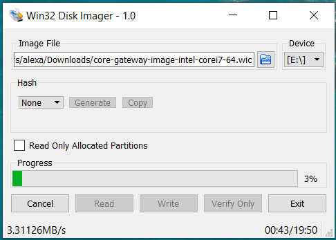
- Start Win32 Disk Imager, select uncompressed WIC file (see the pictures below), select your USB flash drive and press Write button to run the flashing process. Wait until flashing is successfully finished.
# Cable Connections
Warning
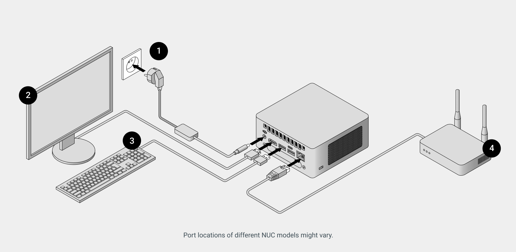
Make the entire assembly process while the gateway is turned off.
Warning
Make sure you’re using the correct type of DC power supply that is specified in the user manual of your NUC model.
- Connect external monitor with HDMI cable.
- Insert USB Keyboard into any USB port.
- Connect to WiFi Router with Ethernet cable.
- Finally, connect Intel NUC to power supply and switch on the gateway. You will see a welcome screen on the connected monitor.
# Disable Secure Boot in Gateway BIOS
Enapter OS will boot from the USB flash. To enable it, Secure Boot must be turned off in BIOS.
To enter the BIOS press F2 button on a keyboard few times right after powering up Intel NUC. If you are facing issues with this step, check this troubleshooting guide (opens new window).
# NUC with Visual BIOS
- Click
Advanced>Boot>Secure Boottab. - Uncheck
Secure Bootoption. - Press
F10. - Select
Yesto save this change. - Reboot the system.
# NUC with Aptio V BIOS
- Click
Boot>Secure Bootoption - Select
Disabledoption forSecure Boot. - Press
F10. - Select
Yesto save this change. - Reboot the system.
# Set Up Gateway Software
Note
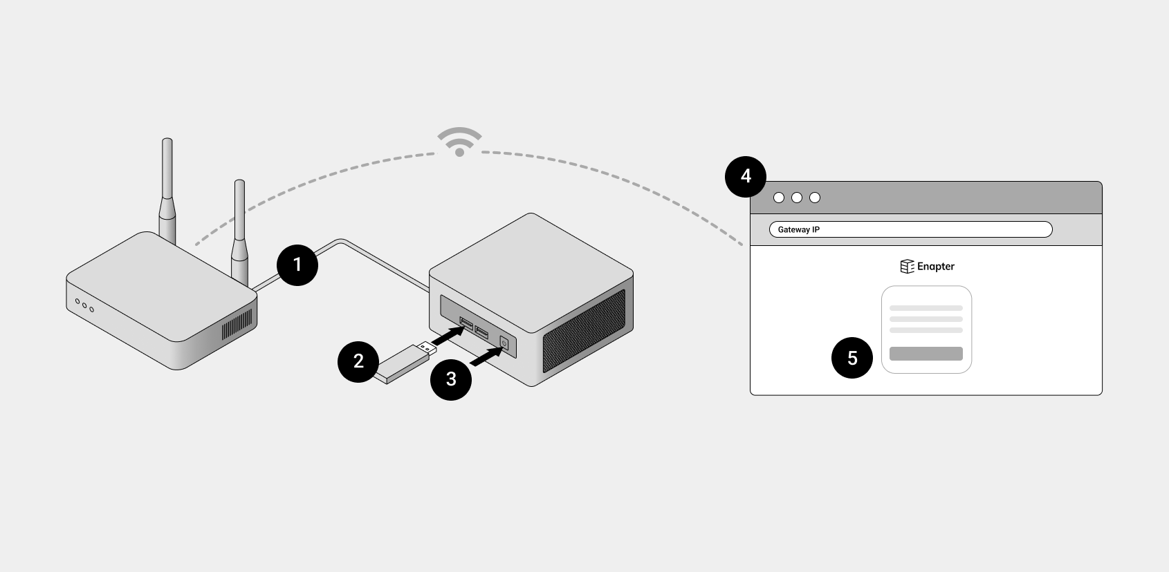
Computer or mobile phone should be connected to the same network as the gateway.
- Make sure gateway is connected to WiFi router via Ethernet cable.
- Insert Bootable USB Flash into any USB port in the Gateway.
- Reboot a the gateway. After reboot you will see Enapter welcome screen on the connected monitor.
- To continue setup you need to access Gateway Web Interface. Open a new tab in the browser on your computer or mobile phone. Enter
enapter-gateway.localinto the address bar. If it doesn’t work, use IP address of Gateway instead (To obtain IP address, enteripcommand on the initial welcome screen. The error may appear if the network is not yet initialized, please try again in one minute). - Follow the on-screen setup instructions to finish the Gateway Software installation.
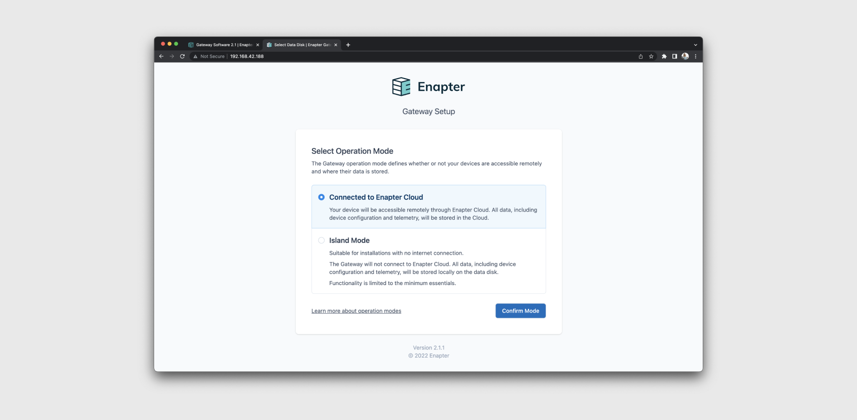
- Choice between Cloud Mode and Island Mode. For more information check Comparison Cloud Mode and Island Mode.
# Installing Gateway Software on the Gateway Disk (optional)
Note
Gateway Software will be installed on the Gateway Data Storage Disk.
Warning
Gateway Software must be version 2.4 or above.
After successfully preparing the hardware part of your Enapter Gateway and completing the initial setup, you have a choice between two options for using your device:
- Continue operating with the operating system loaded from a USB flash drive. Please note that it is recommended to use industrial-grade USB flash drive.
- Install the Gateway Software on the internal disk.
Each of these options has its advantages and disadvantages, and the choice depends on your needs and the conditions in which the device will be operated.
Operating from a USB flash drive offers high flexibility in updating the operating system. You will only need to power off your Enapter Gateway, extract the USB flash drive, update the Gateway Software image using another computer, insert the USB flash drive back, and power on the device.
However, installing the Gateway Software on the internal disk provides a number of significant advantages. Firstly, it eliminates the risk of damaging or losing the flash drive, as nothing sticking out from the PC, making it a safer option if the device is to be left in a hard-to-reach place for a long time. Secondly, internal disks generally have a lower failure rate compared to flash drives, offering more reliability for long-term operation.
It's important to note, however, that the update process for an on-disk installation will require the physical presence of someone on-site, equipped with a USB keyboard and an external monitor. Additionally, at its current state, the process requires some knowledge about the Linux shell, making it essential for the person performing the update to be familiar with basic Linux commands and operations. For more detailed instructions please see the update guide.
To install the Gateway Software on the internal disk:
- Access the Gateway Shell. You can find detailed instructions on how to access the Gateway the guide.
- Once you have successfully connected to the Enapter Gateway device, enter the following command in the shell:
sudo enapter-linux-install
- This command will initiate the installation process for the Gateway Software. Follow the on-screen instructions to complete the installation.
After entering the installation command, you will see a series of messages on your screen as the system proceeds with the installation. Here is an example of what you might see:
enapter@enapter-gateway:~$ sudo enapter-linux-install
Are you sure you want to proceed with installing Enapter Linux on the HDD? (y/n) y
[INFO] Ok, we will proceed.

[INFO] Mounting the HDD boot partition.

mount: /dev/sda2 mounted on /mnt/boot.
[INFO] Copying system files, please wait...

mkdir: created directory '/mnt/boot/EFI'
mkdir: created directory '/mnt/boot/EFI/BOOT'
'/boot/EFI/BOOT/grub.cfg' -> '/mnt/boot/EFI/BOOT/grub.cfg'
'/boot/EFI/BOOT/grubenv' -> '/mnt/boot/EFI/BOOT/grubenv'
'/boot/EFI/BOOT/unicode.pf2' -> '/mnt/boot/EFI/BOOT/unicode.pf2'
'/boot/EFI/BOOT/bootx64.efi' -> '/mnt/boot/EFI/BOOT/bootx64.efi'
'/boot/EFI/BOOT/mmx64.efi' -> '/mnt/boot/EFI/BOOT/mmx64.efi'
'/boot/EFI/BOOT/grubx64.efi' -> '/mnt/boot/EFI/BOOT/grubx64.efi'
mkdir: created directory '/mnt/boot/EFI/enapter'
'/boot/EFI/enapter/version.txt' -> '/mnt/boot/EFI/enapter/version.txt'
'/boot/EFI/enapter/rootfs.img' -> '/mnt/boot/EFI/enapter/rootfs.img'
'/boot/EFI/enapter/initrd' -> '/mnt/boot/EFI/enapter/initrd'
'/boot/EFI/enapter/bzImage' -> '/mnt/boot/EFI/enapter/bzImage'
'/boot/Enapter.cer' -> '/mnt/boot/Enapter.cer'
mkdir: created directory '/mnt/boot/layers'
'/boot/layers/enapter-iot.img' -> '/mnt/boot/layers/enapter-iot.img'
[INFO] Syncing disks.

[INFO] Unmounting the HDD boot partition.

[INFO] Enapter Linux has been successfully installed on the HDD. Please remove the installation media (USB stick) and reboot the PC.
Please note, the actual messages may vary depending on your specific hardware and software versions. This example is provided to give you a general idea of the installation process and the types of messages that confirm successful steps.
If you encounter any error messages during the installation, or experience difficulties in resolving them, or have questions, please do not hesitate to reach out to us on Discord (opens in a new tab) for support.
# ⚙️ Operational Modes
# Comparison Cloud Mode and Island Mode
| Cloud Mode | Island Mode | |
|---|---|---|
| Description | On-site devices will be accessible remotely through Enapter Cloud. All data, including device configuration and telemetry, will be stored in the Cloud. | Most sites that are located in remote areas where internet connection is not easily accessible or is not stable. Even if the Internet connection is available, it is important for business to keep their equipment operational in isolated setups in case of a power outage. That is why Enapter offers Island Mode for Gateway that allows to collect and store data from Enapter devices locally. |
| Historical Data / Monitoring charts | Yes Unlimited free cloud data storage | Yes Limited by Gateway’s data drive storage |
| Commands | Yes | Yes |
| Remote access | Yes | No |
| Sites amount | Unlimited Cloud supports unlimited setups in any location | Only 1 site Gateway supports only one setup |
| Adding 3rd party energy devices | Yes Any vendor device can be added to an energy management system with UCMs and Blueprints | No Only Enapter Electrolysers, Dryers and Water Tanks can be added |
# ☁️ Cloud Mode
# Connecting Gateway to the Enapter Cloud
- Connect and power on all Enapter devices.
- Connect Intel NUC PC with Gateway 2.X software and network equipment according to technical specifications.
- Set up Gateway 2.X software using installation instructions.
- Navigate to your Site in Enapter Cloud (opens new window).
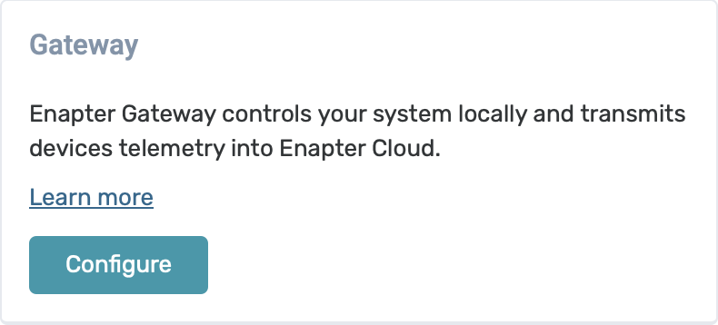
- Click the
Configurebutton in theGatewaysection on the left of the screen.
- Copy the Configuration String to the Clipboard. Click the
Copy to Clipboardbutton.
- Navigate to the local page of your Gateway http://enapter-gateway.local/ (opens new window) or http://gateway_ip/ (opens new window).
- Select the
Connected to Enapter Cloudin the menu. - Paste the Configuration String into the form.
- Click the
Set Up Connectionbutton.
# 🏝️ Island Mode
# Setting Up Gateway in Island Mode
- Connect and power on all Enapter devices.
- Connect Intel NUC PC with Gateway 2.X software and network equipment according to technical specifications.
- Set up Gateway 2.X software using installation instructions.
- Navigate to the local page of your Gateway http://enapter-gateway.local/ (opens new window) or http://gateway_ip/ (opens new window).
- Select the
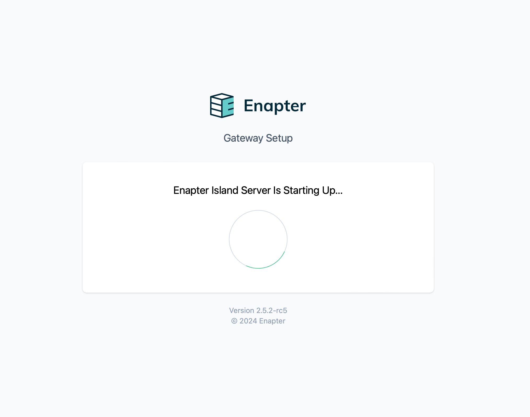
Island Modein the menu. - Please wait until the Island server has started.
# Adding Island Connection to Mobile Application
Note
Mobile phone must be connected to the same network as the Gateway.
- Complete Setting Up Gateway in Island Mode.
- Open Enapter App and navigate to
Moretab. - Open
Accountsand tap on the+Add Island Connection. - Enter IP address of the Gateway, login and superuser password.
# 🔧 Enapter Gateway Factory Reset
A factory reset restores the device to its original factory settings, effectively erasing any configurations, data, or customizations that have been applied since it was first set up.
For more information about Enapter Gateway Factory Reset, please check this guide.
# 🌐 Virtual UCM
If you want to integrate devices connected to an Ethernet or WiFi network and use protocols such as Modbus TCP, HTTP, OPC UA for communication, then you do not need additional hardware modules and all you need is your Enapter Gateway and Enapter vUCM technology.
To integrate devices, you will need to create a device description in YAML format and some Lua code. For more information see our documentation on Enapter Blueprints (opens new window) и vUCM Lua API (opens new window)
# How to Add Virtual UCM
To add Virtual UCM to your Site:
- Set up Enapter Gateway on your Site.
- Open your Site in Enapter Cloud (opens new window).
- Look for
Virtual UCMon the left sidebar and click on theManagebutton. - On the next screen, click the
New Virtual UCMbutton in the top right corner.
# 🛠️ Rule Engine
Gateway firmware 2.x contains a redesigned Rule Engine that allows you to write rules in the Lua language using a convenient web IDE.
Now the Rule Engine supports not only Enapter devices but also any other devices, thanks to Enapter Blueprints technology.
See our Enapter Blueprints (opens new window) and Enapter Rule Engine (opens new window) programming guide for writing rules in Lua.
Also, be sure to check the Use cases section for examples of rules usage.
# Create Enapter Rule
- Open your Site in Enapter Cloud (opens new window).
- Look for
Ruleson the left sidebar and click on theManagebutton. - On the next screen, click the
New Rulebutton in the top right corner.
# 🖥️ Command Line Interface
The CLI of the Enapter Gateway has been changed as of version 2.4. Please refer to the appropriate guide based on your version to ensure proper use of the CLI.
# For Version 2.4 and Newer:
Command Line Interface Guide for Version 2.4 and Newer
# For Versions Prior to 2.4:
Command Line Interface Guide for Versions Prior to 2.4
# 🕸️ Public MQTT API
Note
MQTT API supported for Enapter devices only.
# Configuration
Before starting integration process MQTT API should be configured. If you are not familiar with how to access and use Enapter Command Line interface please see Enapter Command Line Interface section of this documentation.
To do this - enter configuration mode on gateway shell and set basic parameters.
# Setup MQTT Port and Authentication
Note
The process for configuring Public MQTT has been updated in Enapter Gateway version 2.4. Please refer to the version-specific guides below.
For Version 2.4 and Newer: Access the updated guide.
For Versions Before 2.4: Consult the guide.
# Receiving device telemetry
- Connect to mqtt on gateway ip address, specified port, with specified username & password,
- Subscribe to telemetry topic.
mosquitto_sub -d -v -p 9883 -h 192.168.1.1 -u public -P password -t "telemetry/v2/<DEVICE_ID>"
# Device Telemetry API
# Device Telemetry
Provides Device telemetry.
Will be published every 1 second.
telemetry/v2/{DEVICE_ID}
| Payload Field | Description |
|---|---|
timestamp | Message publishing timestamp |
| ... | Device-specific fields |
# Example
Topic
telemetry/v2/4b0bacce-740c-4643-951b-0e5828a6cc1c
Payload
{
  "timestamp": 1514320289,
  "uptime": 2
}
# Device Commands API
# Request Command Execution
commands/v2/{DEVICE_ID}/requests
| Payload Field | Description |
|---|---|
id | Command execution ID, e.g. UUID |
name | Command name |
arguments | Optional, command arguments |
expires | Optional, command expiration timestamp |
# Example
Topic
commands/v2/4b0bacce-740c-4643-951b-0e5828a6cc1c/requests
Payload
{
  "id": "ab3e364c-cab2-4cc1-872d-4d554530d587",
  "name": "impulse",
  "arguments": {
    "id": 1,
    "impulse": 300
  }
}
# Command Execution Responses
commands/v2/{DEVICE_ID}/responses
| Payload Field | Description |
|---|---|
id | Required, command execution ID, e.g. UUID |
state | Required, command execution state, e.g. started |
payload | Optional, command state payload |
# Example
Topic
commands/v2/4b0bacce-740c-4643-951b-0e5828a6cc1c/responses
Payload
{
  "id": "ab3e364c-cab2-4cc1-872d-4d554530d587",
  "name": "finished"
}
# Electrolyser V2.1 Protocol
# Device Telemetry Payload
| Field | Description |
|---|---|
timestamp | Message publishing timestamp |
status | Electrolyser states |
alerts | List of electrolyser errors (opens new window) and warnings (opens new window) |
LSHH102A_in | Indicates whether electrolyte level is higher than very high level |
LSH102B_in | Indicates whether electrolyte level is higher than high level |
LSM102C_in | Indicates whether electrolyte level is higher than medium level |
LSL102D_in | Indicates whether electrolyte level is higher than low level |
h2_flow | H2 Production in Normal Litre/hour |
h2_total | Total H2 Produced in Normal Litre |
PT101A_in_bar | H2 Stack Pressure in Bar |
PSU_in_v | H2 Stack Voltage in Volt |
HASS_in_a | H2 Stack Amperage in Ampere |
PT101C_in_bar | H2 Outlet Pressure in Bar |
PT105_in_bar | Water Inlet Pressure in Bar |
TT102A_in_c | Electrolyte Tank Temperature in Celsius |
TT106_in_c | Downstream Temperature in Celsius |
V105_out_open | Indicates whether water refilling valve is open state |
production_rate | Current production rate in percents |
# Electrolyser States
| State |
|---|
| maintenance |
| expert |
| halt |
| error |
| fatal |
| idle |
| steady |
| standby |
| curve |
| blowdown |
# Example
{
  "TT106_in_c": 24.7,
  "LSH102B_in": false,
  "LSL102D_in": true,
  "LSM102C_in": true,
  "LSHH102A_in": false,
  "TT102A_in_c":  38.3,
  "alerts": ["FP_01", "FP_03"],
  "h2_flow": 250.0,
  "h2_total": 10000,
  "PT101C_in_bar":  30.0,
  "production_rate": 100,
  "HASS_in_a": 12.3,
  "PT101A_in_bar": 30.1,
  "PSU_in_v": 38.1,
  "status": "steady",
  "timestamp": 1514320289,
  "PT105_in_bar": 1.2,
  "V105_out_open": false
}
# Supported Commands
| Command Name | Description | Arguments |
|---|---|---|
start | Start electrolyser | |
stop | Stop electrolyser | |
reset | Reset electrolyser | |
set_production_rate | Set electrolyser production rate (in percents) | value (float) |
set_waterfill | Force electrolyser to perform water refill operation | value (boolean) (should be set to true) |
set_preheat | Start electrolyser pre-heating | value (boolean) (should be set to true) |
# Enapter Dryer Protocol
# Device Telemetry Payload
| Field | Description |
|---|---|
timestamp | Message publishing timestamp |
status | Dryer States |
alerts | List of dryer errors (opens new window) and warnings (opens new window) |
pr0 | H2 Inlet Pressure in Bar |
pr1 | H2 Outlet Pressure in Bar |
# Dryer States
| State |
|---|
| none |
| idle |
| waiting_for_power |
| waiting_for_pressure |
| stopped_by_user |
| starting |
| waiting_for_electrolyser |
| standby |
| waiting_for_rule_engine |
| drying_0 |
| cooling_0 |
| switching_0 |
| pressurizing_0 |
| finalizing_0 |
| drying_1 |
| cooling_1 |
| switching_1 |
| pressurizing_1 |
| finalizing_1 |
| leak_input |
| leak_dryer |
| error |
| bypass |
| bypass1 |
| bypass2 |
| maintenance |
| expert |
# Example
{
  "timestamp": 1547680704,
  "status": "drying_0",
  "pr0": 30.5,
  "pr1": 26.1,
  "alerts": ["TT00", "PT00"]
}
# Supported Commands
| Command Name | Description |
|---|---|
dryer_start | Start dryer |
dryer_stop | Stop dryer |
reboot_dryer | Reboot dryer |
# 💻 OPC UA
OPC UA (Open Platform Communication Unified Architecture) is a secure OT-IT communication standard mostly for industrial equipment. Known by some as “the global production language”, OPC UA enables improved data communication and interoperability between devices and systems in many industries.
Info
Definition, features and more details about OPC UA can be found at opcfoundation.org (opens new window).
# Required Equipment
You will need a Enapter Gateway Software installed to your Intel NUC computer. It provides telemetry, properties and commands for all connected devices over the OPC UA interface, for easier interoperability with industrial systems.
# Enabling OPC UA on the Gateway
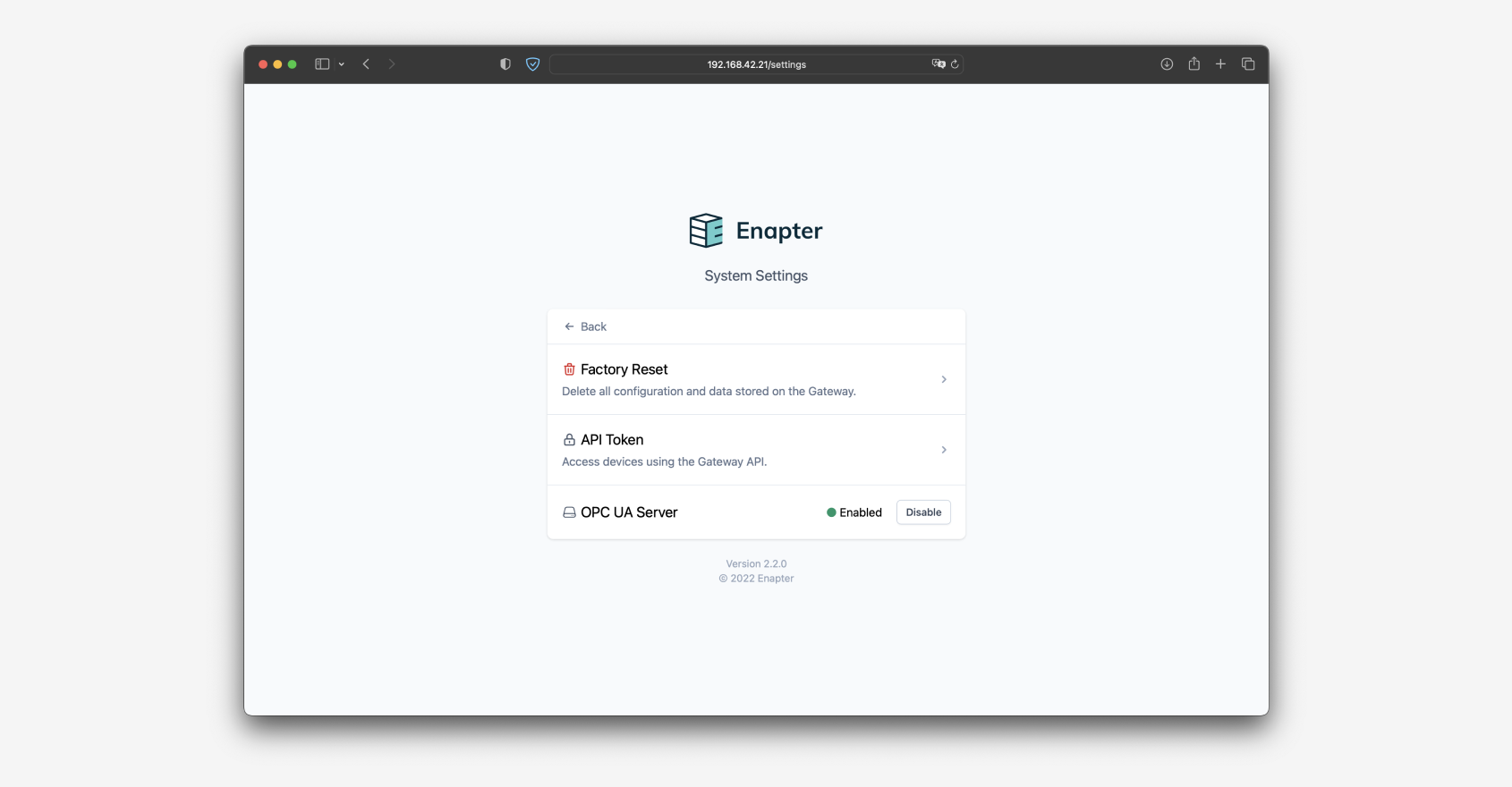
The OPC UA server feature has to be enabled on the settings page available in the Gateway web interface. No further configuration is needed in both Island and Cloud modes: connected devices will automatically appear in the OPC UA nodes tree.
- Install Gateway Software according to this guide.
- Access Web GUI of the Gateway using
http://enapter-gateway.localor IP address. - Click on
Settings. - Click on the
Enablebutton in the OPC UA Server area.
# Connecting to OPC UA Client
Download a OPC UA client, for example UAExpert (opens new window) from Unified Automation. UAExpert is a free download for testing OPC UA connectivity and data flow.
To Connect UAExpert to the Enapter OPC UA Server follow these steps:
- In UAExpert, under
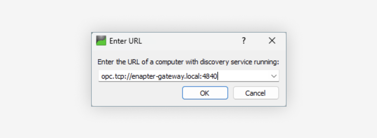
ServerselectAdd…. A dialog will appear with the most recently used servers. Under theCustom Discoverybranch followDouble Click to Add Server…. In the upcoming dialog enter:opc.tcp://enapter-gateway.local.
Info
You need to make sure that your DNS server is resolving this address correctly or you will not be able to connect. You can use the IP address of the Gateway instead of enapter-gateway.local but you might run in security issues with the certificate of the OPC UA Server which uses enapter-gateway.local as its host-name.
Once the URL is showing in the list under
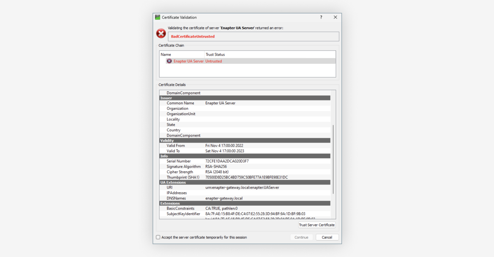
Custom Discoveryyou can double-click the entry to see theEnapter UA Server. If you double-click on this entry, you can choose an encryption for the connection. Pick the one that is closest to the encryption your OPC UA Client will use. The server will then appear on the left side underProject/Servers.To connect to the server, right click the server and select “Connect”. The first time you connect you will be prompted to trust the Self-Signed Server Certificate of the OPC UA Server.
Click the Trust Server Certificate button to accept the certificate then click on Continue.
Info
Under UA Extensions you see the DNSNames: enapter-gateway.local. Some OPC UA Clients are sensitive that this DNS name matches the URL you picked in Step 1 and will reject certificates if the DNS name does not match. We recommend that you make sure your gateway resolves correctly to enapter-Gateway.local in your network.
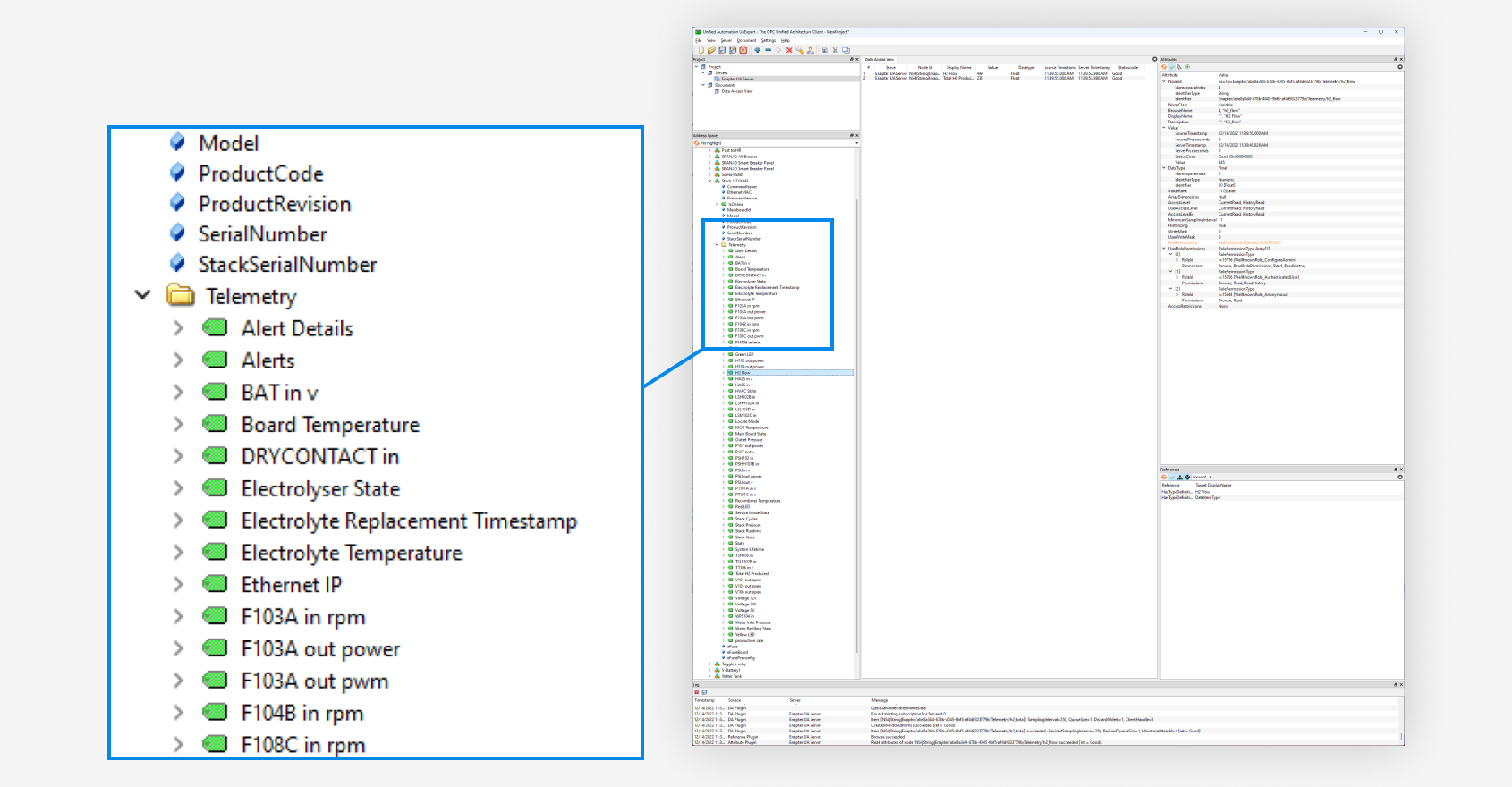
- You can now see all the Devices managed by the Gateway in the
Address Spacearea underRoot/Objects/Enapter.
Each Device is one OPC UA Object. You can navigate the tree to the Properties and Telemetry data of any device. If you drag a Telemetry field to the Data Access View you can see the live value of the field.
All Enapter devices (electrolysers, dryers, water tanks) and any 3rd party device integrated via Enapter Blueprints are exposed the same way in the OPC UA tree.
Note
In future versions of the OPC UA Server, the hierarchy of the object might change.
# 🤖 Creating Enapter Rule (Automation)
- Set up Enapter Gateway on your Site.
- Open your Site in Enapter Cloud (opens new window).
- Look for
Ruleson the left sidebar and click on theManagebutton. - On the next screen, click the
New Rulebutton in the top right corner.
# 💼 Enapter Rule Engine Use Cases
Enapter Rule Engine recipes are available in Developers Documentation (opens new window).
Feel free to ask for a help in Discord (opens in a new tab) .
# 🧠 Updating Gateway Software
# Updating the Gateway Software on the Bootable USB Flash
- Power off the Enapter Gateway.
- Extract the USB flash from the Enapter Gateway.
- Refer to the Create Bootable USB Flash guide to download the latest version of the Enapter Gateway Software. Follow the instructions provided in the guide to write the new software version onto your USB flash drive.
- Insert Bootable USB Flash into any available USB port on the Enapter Gateway. Ensure the drive is securely connected.
- Power on the Enapter Gateway. The internal update process will automatically initiate during the first boot with the updated Gateway Software version on the USB flash drive. This process is designed to run seamlessly, but it's important to not interrupt the power supply during the update.
# Updating the Gateway Software on the Gateway Disk
Before you begin, ensure you have the following items:
- A USB flash drive with a minimum capacity of 16 GB
- An external monitor connected to the Enapter Gateway
- A USB keyboard
Note
These items are necessary to perform the software update process on your Enapter Gateway.
- Refer to the Create Bootable USB Flash guide to download the latest version of the Enapter Gateway Software. Follow the instructions provided in the guide to write the new software version onto your USB flash drive.
- Insert Bootable USB Flash into any available USB port on the Enapter Gateway. Ensure the drive is securely connected.
- Power on the Enapter Gateway and use the computer's BIOS boot menu to select booting from the USB flash drive.
- After a successful boot process, verify that you have booted with the new version of the Enapter Gateway software. The software version is displayed as part of the welcome message.
- Access the Gateway Shell. You can find detailed instructions on how to access the Gateway the guide.
- Once you have successfully connected to the Enapter Gateway device, enter the following command in the shell:
sudo enapter-linux-install
After entering the installation command, you will see a series of messages on your screen as the system proceeds with the installation. Here is an example of what you might see:
$ sudo enapter-linux-install
Are you sure you want to proceed with installation Enapter Linux on HDD? (y/n) y
[INFO] Ok, we will proceed.

[INFO] Mounting the HDD boot partition.

mount: /dev/sda2 mounted on /mnt/boot.

Enapter Linux appears to be already installed on the HDD (/mnt/boot), but the system has booted from a USB. If you wish to overwrite the installed files, please remove them manually.
If you seeing this message and no errors you may proceed.
Please execute the command below to remove the currently installed system files, and then proceed to re-run the installation process:
sudo rm -rf /mnt/boot/*
sudo enapter-linux-install
After entering the installation command, you will see a series of messages on your screen as the system proceeds with the installation. Here is an example of what you might see:
enapter@enapter-gateway:~$ sudo enapter-linux-install
Are you sure you want to proceed with installing Enapter Linux on the HDD? (y/n) y
[INFO] Ok, we will proceed.

[INFO] Mounting the HDD boot partition.

mount: /dev/sda2 mounted on /mnt/boot.
[INFO] Copying system files, please wait...

mkdir: created directory '/mnt/boot/EFI'
mkdir: created directory '/mnt/boot/EFI/BOOT'
'/boot/EFI/BOOT/grub.cfg' -> '/mnt/boot/EFI/BOOT/grub.cfg'
'/boot/EFI/BOOT/grubenv' -> '/mnt/boot/EFI/BOOT/grubenv'
'/boot/EFI/BOOT/unicode.pf2' -> '/mnt/boot/EFI/BOOT/unicode.pf2'
'/boot/EFI/BOOT/bootx64.efi' -> '/mnt/boot/EFI/BOOT/bootx64.efi'
'/boot/EFI/BOOT/mmx64.efi' -> '/mnt/boot/EFI/BOOT/mmx64.efi'
'/boot/EFI/BOOT/grubx64.efi' -> '/mnt/boot/EFI/BOOT/grubx64.efi'
mkdir: created directory '/mnt/boot/EFI/enapter'
'/boot/EFI/enapter/version.txt' -> '/mnt/boot/EFI/enapter/version.txt'
'/boot/EFI/enapter/rootfs.img' -> '/mnt/boot/EFI/enapter/rootfs.img'
'/boot/EFI/enapter/initrd' -> '/mnt/boot/EFI/enapter/initrd'
'/boot/EFI/enapter/bzImage' -> '/mnt/boot/EFI/enapter/bzImage'
'/boot/Enapter.cer' -> '/mnt/boot/Enapter.cer'
mkdir: created directory '/mnt/boot/layers'
'/boot/layers/enapter-iot.img' -> '/mnt/boot/layers/enapter-iot.img'
[INFO] Syncing disks.

[INFO] Unmounting the HDD boot partition.

[INFO] Enapter Linux has been successfully installed on the HDD. Please remove the installation media (USB stick) and reboot the PC.
Please note, the actual messages may vary depending on your specific hardware and software versions. This example is provided to give you a general idea of the installation process and the types of messages that confirm successful steps.
- Power off the Enapter Gateway.
- Extract the USB flash from the Enapter Gateway.
- Power on the Enapter Gateway.
If you encounter any error messages during the installation, or experience difficulties in resolving them, or have questions, please do not hesitate to reach out to us on Discord (opens in a new tab) for support.
Was this page useful?

