# Electrolyser 2.1 Rev A. (EL 2.1 Rev A.)
Warning
The Electrolyser 2.1 Rev A. (EL 2.1 Rev A.) is no longer available for purchase.
Electrolysers 4.1 is the latest available model.
Note
Find all details about service and support management for EL 2.1 units in this document.
Enapter's patented anion exchange membrane (AEM) electrolyser is a standardized, stackable and flexible system to produce on-site hydrogen. Modular design paired with advanced software integration enables set up in minutes and remote control and management. Stack this electrolyser to achieve the required hydrogen flow rate.
- 📖 Resources
- 📸 Images
- 🚀 First Start
- 🚦 Status LEDs Indications
- ⚠️ Events
- 📈 Remote Monitoring and Control
- 🔌 Modbus TCP Interface
- 🖥️ Web GUI
- ☁️ Cloud over Ethernet
- 💧 Refilling and Draining
- 🔧 Maintenance Tasks
- 🕸️ Dryer Control Network
- 💚 Safety Heartbeat
- 💨 Blowdown Routine
- 💻 Firmware
- ⚙️ Factory Settings Reset
- 🆘 Self Service Troubleshooting Flowcharts
- 🐞 Known Hardware Bugs
# 📖 Resources
| Rev. | Availability | Datasheets | Owner's Manuals | Quick Start Guides | Battery Limits | CAD Drawings | Cooling | Power Supply | Narrow Body | Certification | |
|---|---|---|---|---|---|---|---|---|---|---|---|
| Certified | EN | EN | EN | EN | 3D STP 3D IGS | Air cooled | AC | No | CE Certificate (EN) CE Certificate (DE) | ||
| EN | EN | 3D STP 3D IGS | Liquid cooled | ||||||||
| Prototype | EN | EN | 3D STP 3D IGS | Air cooled | DC | Yes |
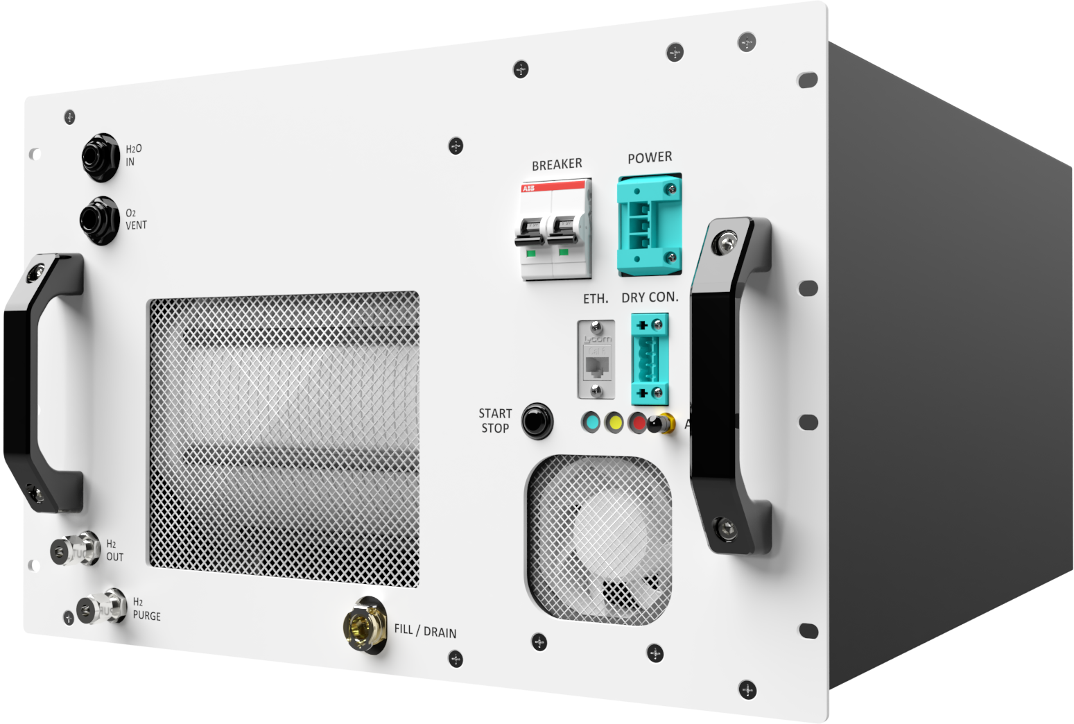
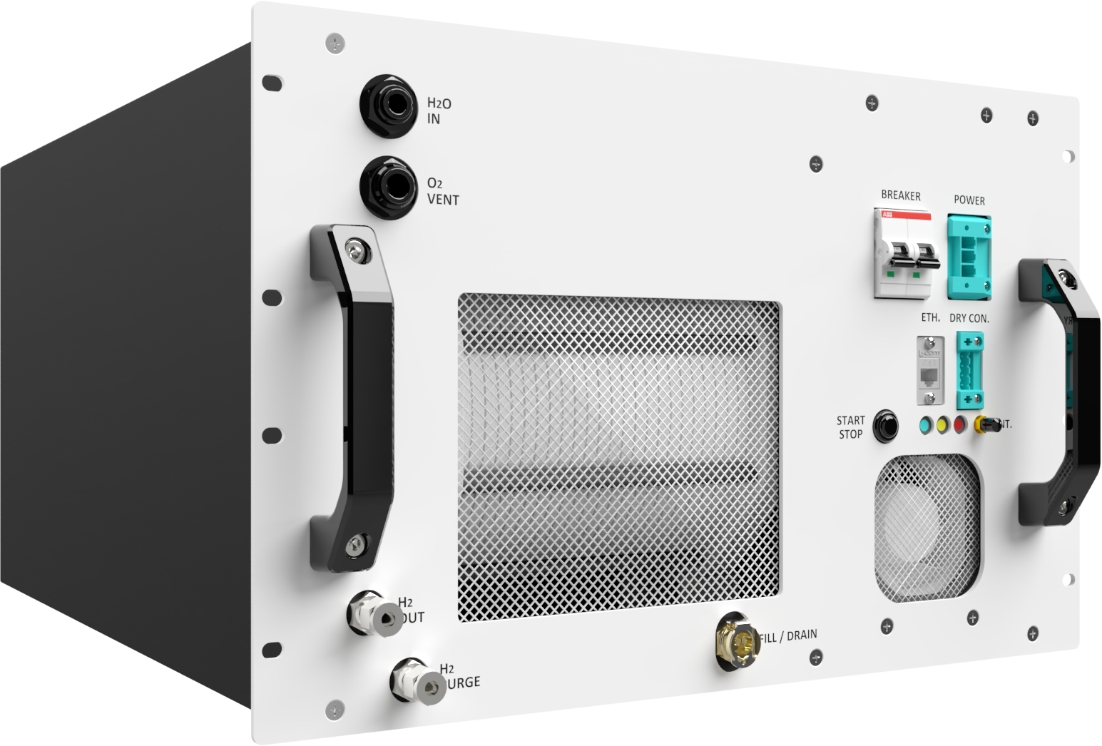
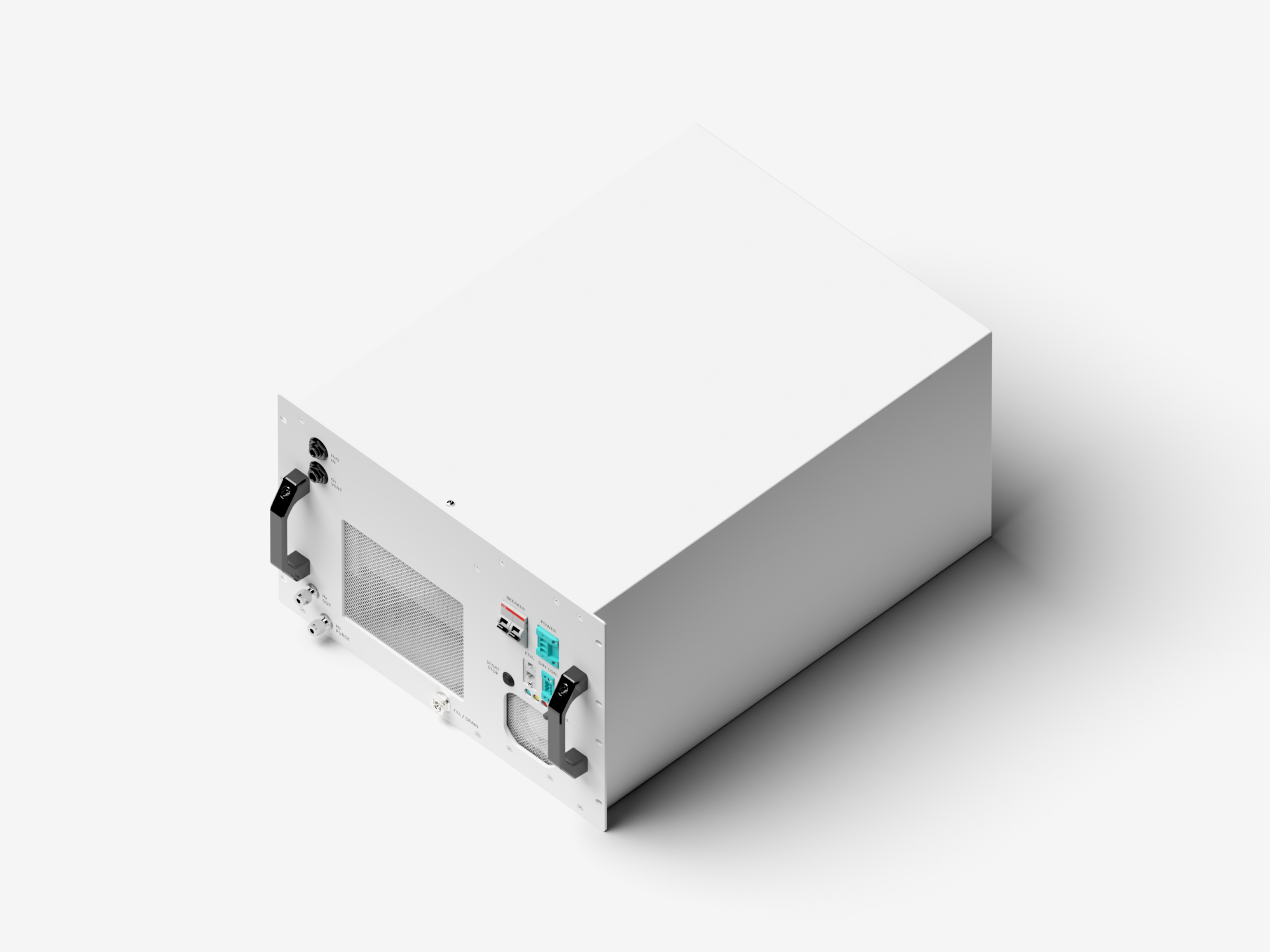
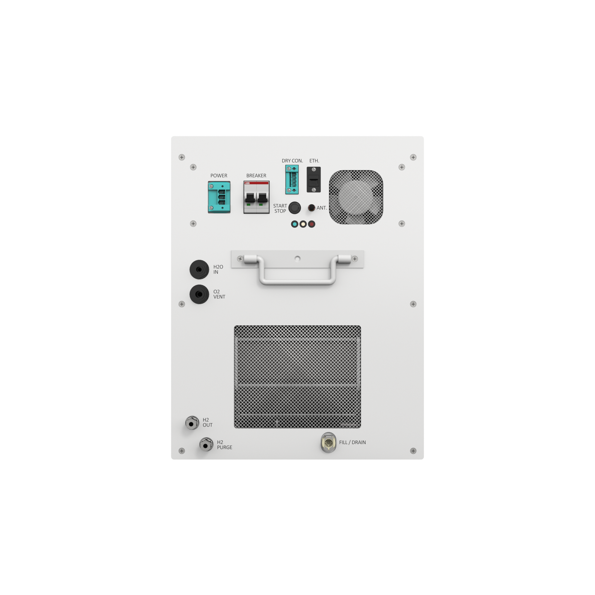
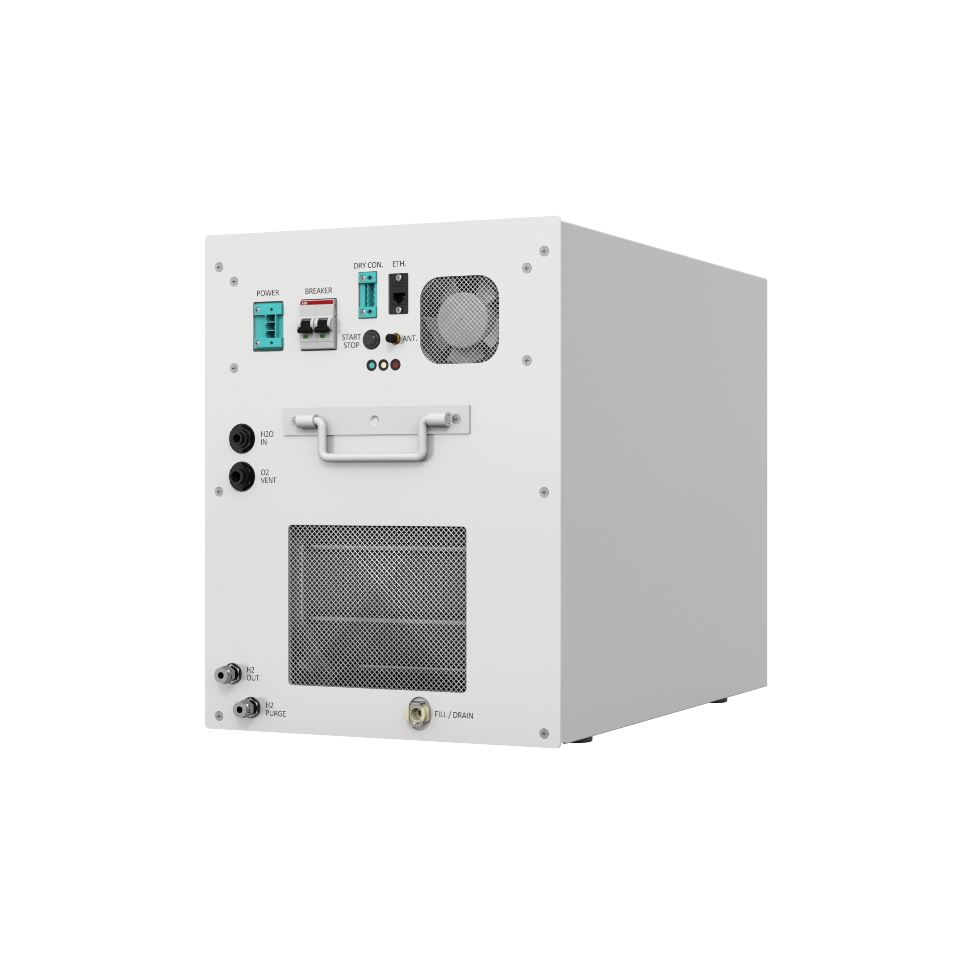
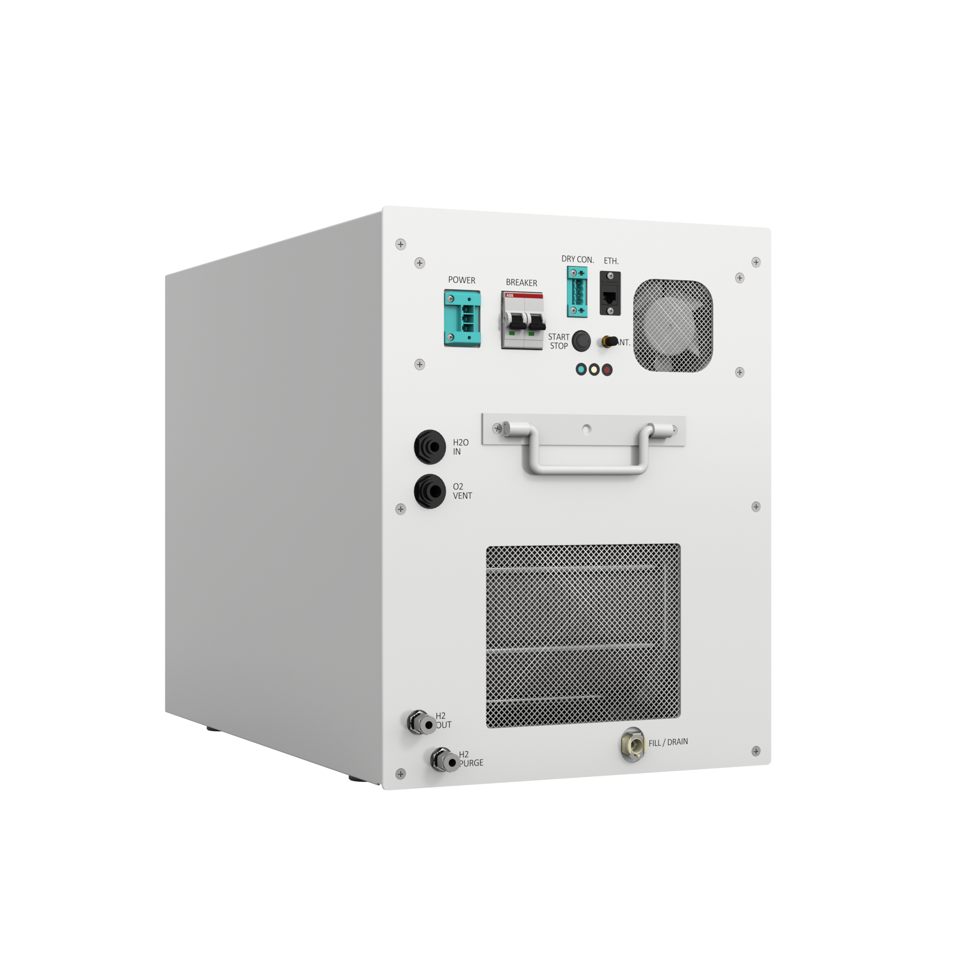
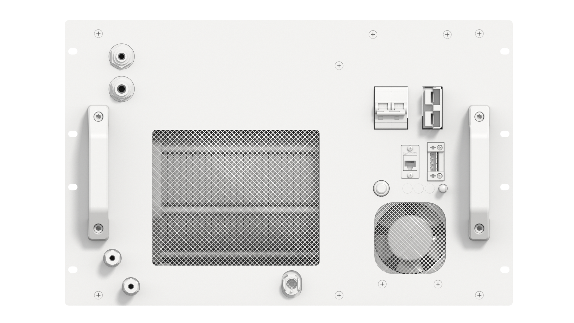
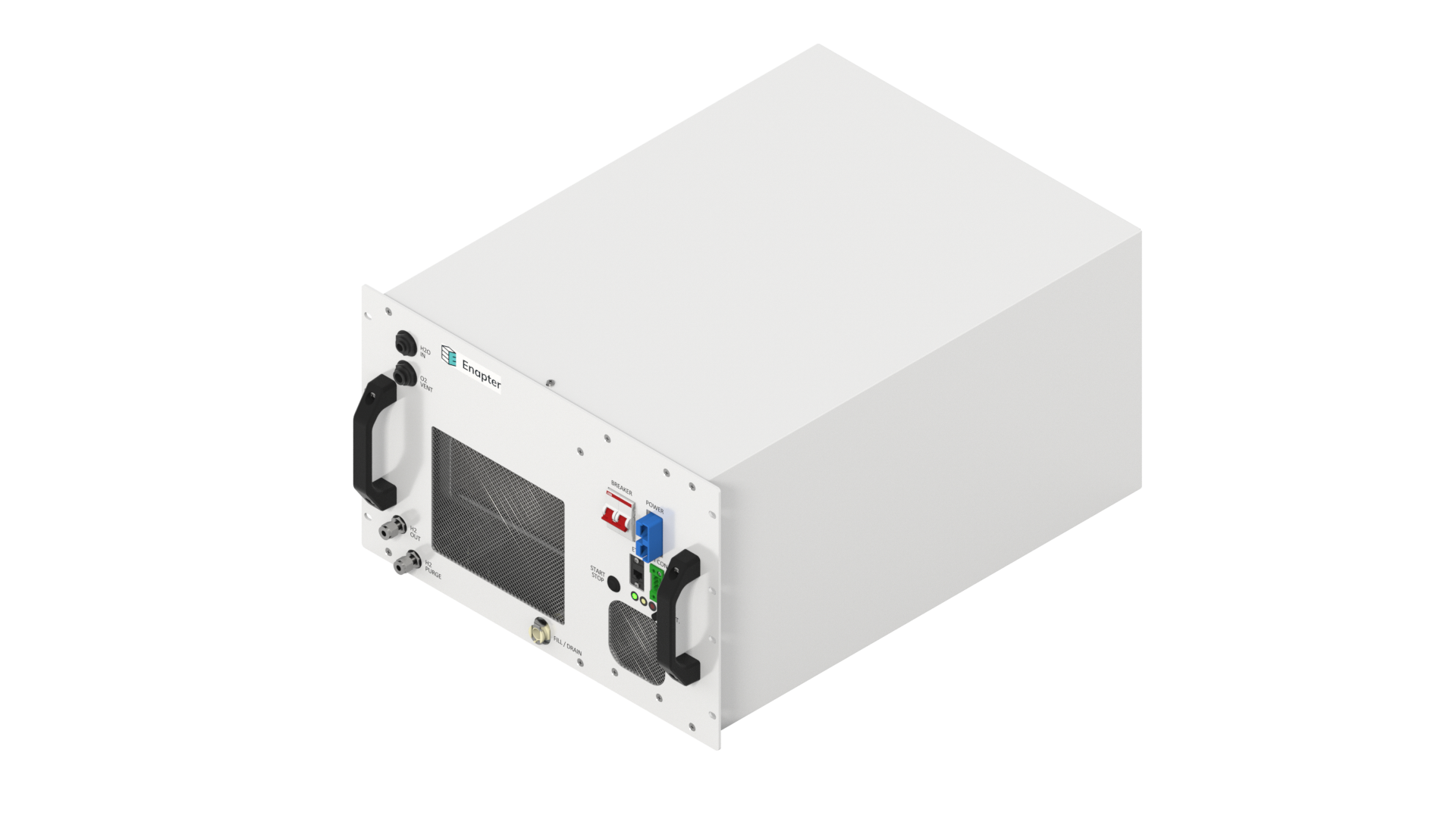
# 📸 Images
| Front | Right Side | Left Side | Isometric | |
|---|---|---|---|---|
| EL 2.1 Rev A. | Download | Download | Download | Download |
| EL 2.1 Rev A. Narrow Body | Download | Download | Download | |
| EL 2.1 Rev A. Direct Current | Download | Download |
# 🚀 First Start
Make sure all pipes and wires are connected.
- You should follow the Enapter EL 2.1 Owner's manual on electrical and piping connections, operation, transportation, storage and disposal steps.
- Insert two supplied jumpers into the Dry Con. port on the front panel of the EL. If a safety chain needs to be integrated, please jump to Dry Contact Connection Guide in Owner's manual.
- Plug in the power cable in the Power Port and turn on the power.
- Electrolyser must be in Maintenance mode.
H2 PURGE and O2 VENT lines.
- It is the installer's responsibility to regularly check and maintain H2 PURGE and O2 VENT lines, as well as to keep the lines free of ice or obstructions.
Warning
Do not insert any check valves or obstructions into the H2 PURGE lines. This can cause irreparable damage to your hydrogen system. No blockage should be present in O2 VENT on the User side of the interface. Never connect H2 PURGE line with O2 VENT line. Mixing these outputs is extremely dangerous.
# With Internet Connection
- Follow the instructions in the Enapter App to connect the device to Enapter Cloud.
- Open the Enapter App and create an account.
- Follow the steps to create a site.
- Add a new device.
- Scan a QR-code located on the front side of the device.
Follow the steps described in The First Refilling.
Electrolyser is ready for use!
# Without Internet Connection
Note
Electrolyser must be updated to firmware 1.6.0 or above.
Connect Electrolyser and access the Web GUI. For more information please check Web GUI Documentation (opens new window).
Follow the steps described in The First Refilling.
Electrolyser is ready for use!
# 🚦 Status LEDs Indications
| Action | Description | LED | |
|---|---|---|---|
 | Power on | The device will turn on as soon as the required input voltage is supplied to the EL2.1 and perform a startup self-check. | Red, yellow & green blink thrice |
 | Stand-by (Idle state) | The device is idle, waiting for the start of production. | Red, yellow & green are off |
 | Stand-by (Max pressure state) | The device reached maximum pressure (normally 35 bar) and will resume hydrogen production automatically when the restart output pressure setpoint is reached. | Green blinking |
 | Steady | The device in steady state. | Green steady |
 | Button press | When the start-stop button is pressed. | Red, yellow & green blink once |
 | Factory Settings Reset | Simultaneously pressing the start-stop button and power up the device will activate Factory Settings Reset. | Running fire (each LED blinks after another) |
 | Maintenance mode | The device is in maintenance mode. | Yellow steady |
 | Locate device | When locate device is enabled via remote control. | Red, yellow & green blinking |
 | Warning | Heads-up event which should be taken into account to avoid Error or Fatal Error. | Yellow Blinks |
 | Error | System Stopped. Recoverable error. | Red Blinks |
 | Fatal Error | System stopped. Unrecoverable error. Hardware repair required. Please contact Enapter support. | Red and Yellow Blinks |
  | Panic | System stopped. Unrecoverable error. Please contact Enapter support. | Red steady with green steady (hardware problem) or yellow steady (software problem) |
# ⚠️ Events
Note
All events listed below correspond with the latest firmware.
# Severity Levels
| Code | Severity Level | LED Indication | Description | Comment |
|---|---|---|---|---|
| F | Fatal Error | Red and Yellow Blinks | System stopped. Unrecoverable error. Hardware repair required. | e.g. Pressure sensor is not connected or broken. |
| E | Error | Red Blinks | System Stopped. Recoverable error. | e.g. No input water pressure and internal water tank is empty. |
| W | Warning | Yellow Blinks | Heads-up event which should be taken into account to avoid Error or Fatal Error. | e.g. No input water pressure and internal water tank is full. |
# Routines
| Code | Routine | Comment |
|---|---|---|
| P | Platform | |
| C | Electrolyte Pump | |
| D | Stack Ramp Down | |
| R | Water Refilling | |
| S | Steady Hydrogen Production | |
| T | Electrolyte Heater | |
| U | Stack Ramp Up | |
| X | Safety Check | |
| F | Anti-freezing | |
| L | Leakage Test | |
| O | Blowdown | |
| H | Heartbeat | |
| Z | Polarization Curve |
# Warning, Error and Fatal Error Codes
Note
The Code and Name marked in bold are introduced in the current release of firmware.
| Code | Name | Severity Code | Routine Code | Component | Condition | Description | Troubleshooting |
|---|---|---|---|---|---|---|---|
| 0x0000 | none | -- | -- | -- | No error | ||
| 0xFFF | int | -- | -- | -- | Unexpected hardware failure | Internal error | Please contact Enapter Customer Support. Unexpected error, not further specified. Please read the logs for details. |
| 0x1F81 | FP_01 | F | P | -- | Voltage < 2.9V | Brownout detected | System detected a brownout. Please restore power and reset the system. |
| 0x1F82 | FP_02 | F | P | -- | Updated firmware has new mandatory settings | New configuration parameters added | Please contact Enapter Customer Support to configure the new system parameters. |
| 0x1F83 | FP_03 | F | P | -- | Hardware failure | Broken periphery | Please contact Enapter Customer Support. An unexpected error has occurred. |
| 0x3F84 | WP_04 | W | P | -- | Power Button pressed for longer than 5sec | Stuck power button | Power button was pressed for too long. Please release the button. |
| 0x3F85 | WP_05 | W | P | CR2032 battery on control board | CR2032 battery voltage is low | Low battery voltage | Please contact Enapter Customer Support. Main board battery charge is too low. |
| 0x1F86 | FP_06 | F | P | Control board MCU | Not enough free RAM | Insufficient resources for DCN/IDCN | Please contact Enapter Customer Support. Not enough hardware resources available to enable DCN/IDCN support. |
| 0x108A | FC_10 | F | C | P107 | Pump voltage too high | Pump broken | Please contact Enapter Customer Support. The electrolyte pump may be broken. |
| 0x1114 | FD_20 | F | D | PT101A | PT101A pressure drop > 2% | Inner hydrogen pressure reading is below the expected value | Please contact Enapter Customer Support. The inner hydrogen pressure transmitter detected a non-nominal pressure drop during the ramp down leakage test. |
| 0x318A | WR_10 | W | R | PT105 | Water inlet pressure > 4 barg | Water inlet pressure is too high | Water inlet pressure has exceeded 4 barg. The automatic refilling will not work. |
| 0x3194 | WR_20 | W | R | PT105 | Water inlet pressure < 1 barg | Water inlet pressure is too low | Insufficient water inlet pressure. The automatic refilling will not work. |
| 0x118A | FR_10 | F | R | LSHH102A | Water level triggers high level switch (LSHH102A) | Electrolyte level is too high | Electrolyte level is too high. Please interrupt the water supply to the system and contact Enapter Customer Support. |
| 0x1194 | FR_20 | F | R | LSL102D | Water level is below the low level switch (LSL102D) | Electrolyte level is too low | Please switch the Electrolyser into maintenance mode, drain it fully, and then fill the electrolyte tank with fresh electrolyte solution. |
| 0x11B2 | FR_50 | F | R | LSL102D LSM102C | LSM102C active and LSL102D inactive | Conflict between water level sensors (low and medium) | Please contact Enapter Customer Support. Internal water sensors may be stuck (conflict between low and medium levels). |
| 0x11B3 | FR_51 | F | R | LSM102C LSH102B | LSH102B active and LSM102C inactive | Conflict between water level sensors (medium and high) | Please contact Enapter Customer Support. Internal water sensors may be stuck (conflict between medium and high levels). |
| 0x11B4 | FR_52 | F | R | LSH102B LSHH102A | LSHH102A active and LSH102B inactive | Conflict between water level sensors (high and very high) | Please contact Enapter Customer Support. Internal water sensors may be stuck (conflict between high and very high levels). |
| 0x11A8 | FR_40 | F | R | -- | Refilling unsuccessful | Please contact Enapter Customer Support. Refilling was unsuccessful. | |
| 0x3195 | WR_21 | W | R | -- | Water refilling time has exceeded the limit | Refilling timeout | Reboot the device and verify that the water inlet requirements are fulfilled. |
| 0x3196 | WR_22 | W | R | -- | Refilling failure | Refilling has failed. Please check your water supply system. | |
| 0x31B3 | WR_51 | W | R | LSL102D | Drain completely | Electrolyte level is below the minimum. The Electrolyser is ready to be refilled. | |
| 0x31B4 | WR_52 | W | R | LSL102D | Refill to high level | Continue filling the electrolyte until it reaches the high level.. | |
| 0x31B5 | WR_53 | W | R | LSH102B | LSHH102A switch triggered | Drain to high level | Electrolyte level is above the high level (overfilling), please drain to the high level. |
| 0x1201 | FS_01 | F | S | PSU 48V | Wrong current value of 48V PSU | Broken PSU | Please contact Enapter Customer Support. PSU might be broken. |
| 0x120A | FS_10 | F | S | PT101A PSU 48V | Broken membrane | Please contact Enapter Customer Support. Stack membrane might be broken. | |
| 0x3215 | WS_21 | W | S | PT101A | PT101A spike > 2% | Drift in inner hydrogen pressure sensor | Please contact Enapter Customer Support. Inner hydrogen pressure mismatch has been detected. |
| 0x3216 | WS_22 | W | S | LSM102C | Refilling is not occurring | Please check the water supply. If not fixed soon, hydrogen production will stop. | |
| 0x321E | WS_30 | W | S | -- | Stack voltage is too high | Replace electrolyte | The electrolyte quality has dropped. Replace the electrolyte. If the error persists, contact Enapter Customer Support. |
| 0x128A | FT_10 | F | T | TT106 | TT106 temperature > 58°C | Electrolyte temperature is too high | Please make sure that the air ventilation is not obstructed or the liquid cooling loop is operating properly as well as the ambient temperature does not exceed the device specifications. If the error persists, please contact Enapter Customer Support. |
| 0x3294 | WT_20 | W | T | F103A | F103A rotation < 600rpm | Electrolyte cooling fan broken | Please contact Enapter Customer Support. The electrolyte cooling fan must be checked. |
| 0x3295 | WT_21 | W | T | TT102A | TT102A temperature is not increasing or increasing too slow | Slow electrolyte heating | Electrolyte temperature is not increasing as expected. Please check the environmental conditions and contact Enapter Customer Support if the warning persists. |
| 0x228A | ET_10 | E | T | TT102A | TT102A temperature < 6°C | Electrolyte temperature is too low | Please make sure that the room temperature is at least 6°C. Keep the EL powered to ensure that the heating routine continues to protect the device internals. |
| 0x330A | WU_10 | W | U | PT101A | Inner pressure > atmospheric pressure + 10% | Gas-side pressure is not atmospheric | Hydrogen Vent (Hydrogen Purge) line pressure detected. Ramp-up is not possible. Please check that the Hydrogen Vent (Hydrogen Purge) line is not obstructed. |
| 0x230A | EU_10 | E | U | LSM102C | Electrolyte level in the internal electrolyte tank is below the medium level | Not enough water for warm-up | Heater cannot be started due to insufficient electrolyte level in the internal electrolyte tank. Refill the electrolyte, reset the system, and try again. |
| 0x2401 | EX_01 | E | X | PT101A | PT101A pressure > 37 for EL 2.1 35 bar PT101A pressure > 9 for EL 2.1 8 bar | Inner hydrogen pressure is too high | Please contact Enapter Customer Support. The inner hydrogen pressure has exceeded 37 (or 9) barg (nominal, but high). |
| 0x1402 | FX_02 | F | X | WPS104 | WPS104 triggered | Water presence detected | Please contact Enapter Customer Support. Water is leaking inside the Electrolyser. Please remove the water supply and power from the system and drain immediately. |
| 0x1403 | FX_03 | F | X | PSU 48V | No voltage on PSU output | PSU broken | Please contact Enapter Customer Support. PSU failure detected. No voltage on stack. |
| 0x1404 | FX_04 | F | X | HASS | HASS current > 58A | Stack current is too high | Please contact Enapter Customer Support. Stack overcurrent detected. |
| 0x1405 | FX_05 | F | X | TSH106 | Backflow temperature is too high | Please contact Enapter Customer Support. The stack outlet temperature is too high. | |
| 0x1407 | FX_07 | F | X | TS108 | TS108 temperature > 75°C | Control board temperature is too high | The control board temperature is too high. Please check and clean air ventilation holes. If the error persists, contact Enapter Customer Support. |
| 0x1408 | FX_08 | F | X | PSH102 | PSH102 switch triggered | Electrolyte tank pressure is too high | Please make sure that the Oxygen Vent line is not blocked. |
| 0x1409 | FX_09 | F | X | TSLL102B | TSLL102B switch triggered | Electrolyte temperature is too low | Please make sure that the ambient temperature is at least 6°C. Keep the Electrolyser powered to ensure the heating routine continues to protect the device internals. |
| 0x140A | FX_10 | F | X | PSHH101B (for Electrolysers with product codes: ELE210535A2AXV04, ELE210508A2AXV04, ELE210535A2LSV01, ELE210508A2LXV01, ELE210535D4AXV01, ELE210508D4AXV01, ELE210535A2ASV05, ELE210508A2ASV05, ELE210535A2ASV06, ELE210508A2ASV06), PT101A | PSHH101B switch triggered PT101A voltage > 3.5V | Hydrogen pressure is too high | Please contact Enapter Customer Support. The pressure transmitter calibration needs to be verified. |
| 0x140B | FX_11 | F | X | Control Board MCU | MCU temperature > 75°C | Control Board MCU temperature is too high | Please make sure that the ambient temperature is below 45°C. |
| 0x140C | FX_12 | F | X | PT101C | Outer hydrogen pressure is too high | Please contact Enapter Customer Support. The calibration of the pressure transmitter needs to be verified. | |
| 0x141E | FX_30 | F | X | PT105 | PT105 readings are outside of the allowed range | Water inlet pressure transmitter broken | Please contact Enapter Customer Support. The water inlet pressure cannot be measured. |
| 0x141F | FX_31 | F | X | TT102A | TT102A readings are outside of the allowed range | Electrolyte tank temperature transmitter broken | Please contact Enapter Customer Support. The temperature of the electrolyte tank cannot be measured. |
| 0x1420 | FX_32 | F | X | FM106 | FM106 readings are outside of the allowed range | Electrolyte flow meter broken | Please contact Enapter Customer Support. The electrolyte flow cannot be measured. |
| 0x1421 | FX_33 | F | X | TT106 | TT106 readings are outside of the allowed range | Electrolyte backflow temperature transmitter broken | Please contact Enapter Customer Support. The temperature of the electrolyte backflow cannot be measured. |
| 0x1422 | FX_34 | F | X | PT101A | PT101A readings are outside of the allowed range | Inner hydrogen pressure transmitter broken | Please contact Enapter Customer Support. The inner hydrogen pressure cannot be measured. |
| 0x1423 | FX_35 | F | X | PT101C | PT101C readings are outside of the allowed range | Outer hydrogen pressure transmitter broken | Please contact Enapter Customer Support. The outer hydrogen pressure cannot be measured. |
| 0x1424 | FX_36 | F | X | F1084B | F108B rotation < 3000 rpm | Chassis circulation fan broken | Please contact Enapter Customer Support. The chassis air circulation fan speed cannot be measured. |
| 0x1425 | FX_37 | F | X | F108C | F108C rotation < 3000 rpm | Electronic compartment cooling fan broken | Please contact Enapter Customer Support. The speed of the electronic compartment cooling fan cannot be measured. |
| 0x1426 | FX_38 | F | X | TS108 | TS108 readings are outside of the allowed range | Electronic board temperature transmitter broken | Please contact Enapter Customer Support. The temperature of the electronic board cannot be measured. |
| 0x1427 | FX_39 | F | X | HASS | HASS readings are outside of the allowed range | Stack current sensor broken | Please contact Enapter Customer Support. The stack current cannot be measured. |
| 0x1428 | FX_40 | F | X | External circuit or switch | Safety circuit open | Dry contact triggered | Dry contact triggered system stop. Please check your control system to understand what triggered the dry contact. |
| 0x3432 | WX_50 | W | X | PT101A | Inner hydrogen pressure check disabled | Please contact Enapter Customer Support. Safety routine check for inner hydrogen pressure is disabled. | |
| 0x3433 | WX_51 | W | X | WPS104 | Water presence check disabled | Please contact Enapter Customer Support. Safety routine check for water presence is disabled. | |
| 0x3434 | WX_52 | W | X | PSU 48V | Power supply unit check is disabled | Please contact Enapter Customer Support. Safety routine check for the power supply unit is disabled. | |
| 0x3435 | WX_53 | W | X | HASS | Stack current check disabled | Please contact Enapter Customer Support. Safety routine check for the stack current is disabled. | |
| 0x3436 | WX_54 | W | X | TSH106 | Electrolyte backflow temperature check disabled | Please contact Enapter Customer Support. Safety routine check for the electrolyte backflow temperature is disabled. | |
| 0x3437 | WX_55 | W | X | TS108 | Control board temperature check disabled | Please contact Enapter Customer Support. Safety routine check for the control board temperature is disabled. | |
| 0x3438 | WX_56 | W | X | PSH102 | Electrolyte tank pressure check disabled | Please contact Enapter Customer Support. Safety routine check for the electrolyte tank pressure is disabled. | |
| 0x3439 | WX_57 | W | X | TSLL102B | Low electrolyte temperature check disabled | Please contact Enapter Customer Support. Safety routine check for the low electrolyte temperature is disabled. | |
| 0x343B | WX_59 | W | X | PT105 | Water inlet pressure check disabled | Please contact Enapter Customer Support. Safety routine check for the inlet pressure (PT105) is disabled. | |
| 0x343C | WX_60 | W | X | TT102A | Electrolyte tank temperature check disabled | Please contact Enapter Customer Support. Safety routine check for the electrolyte tank temperature is disabled. | |
| 0x343D | WX_61 | W | X | FM106 | Electrolyte flow meter check disabled | Please contact Enapter Customer Support. Safety routine check for the electrolyte flow meter (FM106) is disabled. | |
| 0x343E | WX_62 | W | X | F103A V106 | Electrolyte cooling fan check disabled | Please contact Enapter Customer Support. Safety routine check for the electrolyte cooling fan is disabled. | |
| 0x343F | WX_63 | W | X | TT106 | Electrolyte backflow temperature check disabled | Please contact Enapter Customer Support. Safety routine check for the electrolyte backflow temperature is disabled. | |
| 0x3440 | WX_64 | W | X | PT101C | Outer hydrogen pressure check disabled | Please contact Enapter Customer Support. Safety routine check for the outer hydrogen pressure is disabled. | |
| 0x3441 | WX_65 | W | X | F104B | Chassis circulation fan check disabled | Please contact Enapter Customer Support. Safety routine check for the chassis circulation fan is disabled. | |
| 0x3442 | WX_66 | W | X | F108C | Electronic compartment cooling fan check disabled | Please contact Enapter Customer Support. Safety routine check for the electronic compartment cooling fan is disabled. | |
| 0x3443 | WX_67 | W | X | Dry contact | Dry contact check disabled | Please contact Enapter Customer Support. Safety routine check for the dry contact is disabled. External dry signal will be ignored. | |
| 0x3445 | WX_69 | W | X | MCU | Control Board temperature check disabled | Please contact Enapter Customer Support. Safety routine check for the Control Board temperature is disabled. | |
| 0x148A | FF_10 | F | F | -- | Frozen pipes | Please contact Enapter Customer Support. Electrolyte flow is outside pump control limits. | |
| 0x1501 | FL_01 | F | L | -- | Inner hydrogen pressure reading is below the expected value | Please contact Enapter Customer Support. Pressure readings are below nominal values. The device needs to be checked or repaired. | |
| 0x350A | WL_10 | W | L | PT101A | Insufficient pressure drop | The pressure drop across the Hydrogen Vent line from the Electrolyser is insufficient. Check that the line is not obstructed. | |
| 0x358A | WO_10 | W | O | PT101C | Outer pressure > 25 barg | Outer hydrogen pressure is too high for blowdown | Please lower the outer hydrogen pressure below 25 bar in order to start the blowdown routine. |
| 0x3594 | WO_20 | W | O | -- | Blowdown routine enabled | Blowdown routine is active | The blowdown procedure will start once hydrogen production starts. Please ensure that the Hydrogen Purge line is correctly connected and routed to a safe area. |
| 0x159E | FO_30 | F | O | PT101A CV101B | Inner pressure has exceeded the allowed threshold | Hydrogen Purge line obstruction or blowdown failure | The Hydrogen Purge line is obstructed or the adjustable check valve (CV101B) cracking pressure is set incorrectly. Please verify that the Hydrogen Purge line is unobstructed, enable Blowdown for the next hydrogen production cycle, and reset the system. Please contact Enapter Customer Support. |
| 0x360A | WH_10 | W | H | Ethernet Modbus TCP | Heartbeat packet was not received in time | Lost Modbus safety heartbeat communication | Modbus communication between the Electrolyser and the Modbus master device has been lost. Please check that the Ethernet cable is properly installed, the connection is established, and the Modbus master is operational. |
| 0x360B | WH_11 | W | H | Wireless (Wi-Fi) Enapter Gateway | Heartbeat packet was not received in time | Lost Enapter Gateway safety heartbeat communication | Communication between the Electrolyser and the Enapter Gateway has been lost. Please check that the Wi-Fi connection is stable and ensure that the Gateway is operational. |
| 0x360C | WH_12 | W | H | Control Board UCM | Heartbeat packet was not received in time | Lost UCM communication | Lost communication between the Control Board and the UCM (Universal Communication Module). Please contact Enapter Customer Support. |
| 0x368A | WZ_10 | W | Z | -- | Polarization curve start failed | Please contact Enapter Customer Support. |
# 📈 Remote Monitoring and Control
# Introduction
# Network Requirements
# WI-Fi Requirements
802.11a/b/g/n (2.4 GHz only)
802.12 WEP, WPA, WPA2 Personal (Pre-shared key)
Wi-Fi client isolation must be disabled
Note
No captive portal or WPA2 Enterprise supported.
General Wi-Fi Note
The Enapter Cloud connection based on wireless communication and therefore functionality can be affected by distance between devices, obstructions between the devices, and interference. Communication module inside Electrolyser works in station mode and utilizes Wi-Fi channel set in your infrastructure Wi-Fi router for used SSID. You are responsible for selecting the correct channel according to the local radio regulations.
# TCP/IP Network Requirements
| Port | Protocol | Destination Host (IP-Address / Range or Name) |
|---|---|---|
| 80 | TCP | 193.9.249.0/24 (api.enapter.com) |
| 443 | TCP | 193.9.249.0/24 (api.enapter.com) |
| 123 | UDP | 193.9.249.0/24 (ntp.enapter.com) |
| 8883 | TCP | 193.9.249.0/24 (mqtt.enapter.com) |
| 1883 | TCP | 193.9.249.0/24 (mqtt.enapter.com) |
Note
Firewall must be stateful.
# Connecting your Electrolyser to Wi-Fi
To connect your EL 2.1 Electrolyser to a wireless network, follow steps in the iOS or Android Mobile Application guides below. Please note, the QR-code or preinstalled UCM ID and PIN are required when connecting to Wi-Fi as well as credentials for the 2,4 GHz Wi-Fi network.
📗 Enapter iOS Mobile Application Guide
📗 Enapter Android Mobile Application Guide
During connection to Wi-Fi network the QR-code or preinstalled UCM ID and PIN are needed. The location of both of them is displayed in pictures below.
Front view:


Rear view:


# How to Connect the Electrolyser to SCADA?
SCADA is a control system architecture comprising of computers, networked data communications, and graphical user interfaces (GUI) for high-level process supervisory management.
The EL 2.1 Electrolyser can be integrated into SCADA system with Modbus TCP protocol. Alternatively MQTT interface can be used when Enapter Gateway is used.
# Modbus TCP SCADA / PLC Connection
# With Dryer Control Network (DCN)

In this case Dryer and Electrolyser or Electrolysers are connected over the Dryer Control Network. Dryer can be monitored and controlled using the Modbus TCP of any Electrolyser in the Dryer Control Network.
# Standalone (Without The Dryer Control Network)

In this case Dryer will be fully automatic with no monitoring and control.
# MQTT Interface SCADA / PLC Connection

In this case Dryer and Electrolyser or Electrolysers are connected over MQTT protocol using Enapter Gateway. Dryer can be monitored and controlled. Also, Enapter Rule Engine can be used to implement various rules to control and monitor Dryer.
# Connection Testing
Schneider Electric Modbus Tester (opens new window) is a convenient way to test Modbus TCP connection on Windows PC.

Note
The DHCP server or static IP address must be configured and enabled on the PC connected to Electrolyser.
If you are using router connected to Electrolyser the DHCP mode must be enabled.
# Example: Reading Heartbeat Register

TCP/IP Address or URL - enter the IP address of Electrolyser.
Sample mode:
Manual- manual reading.Scheduled- rereading.
Sample Rate in ms - Rereading period.
2000 ms = 2 s
Data type - Holding or Input registers.
The list of all Holding and Input registers can be found at Latest Modbus TCP Interface.
Register number must be plus
1.Heartbeat ModBus Timeout -
4600+1=4601Reading:
- for
Manual- single read. - for
Scheduled- start of rereading.
- for
Read value.
Read value = 2 = 2000 ms.
# Syslog
Note
Electrolyser must be updated to firmware 1.8.0 or above.
Syslog is a Message Logging Standard by which almost any device or application can send data about status, events, diagnostics, and more.
Syslogging can be enabled in two ways:
- Using Modbus register.
- Using Web GUI of Electrolyser.
# Using Modbus Register
The following registers need to be configured to enable Syslog using Modbus:
Holding Register
4042- Data type - Int32
- Name - System logs
- Severity:
0= disable logging (default)1= only fatal errors2= fatal errors and errors3= warnings and more important4= everything before and important messages5= all messages, except internal debug ones6= all messages
Holding Register
4044- Data type - Uint32
- Name - Syslog IP Address
- Default value
255.255.255.255(Broadcast)
Holding Register
4046- Data type - Uint16
- Name - Syslog Port
- Default port
514
# Using Web GUI
System logs can be configured using the Web GUI of Electrolyser. Please check the Syslog Configuration (opens new window) paragraph of the Web GUI documentation.
# Receiving Syslogs
Tftpd64 (opens new window) can be handy to receive system logs on Windows PC.

- Enable system logging using Modbus Registers or Web GUI.
- Tap on the
Syslog server - You will receive system logs depending on chosen severity.
# Altitude Compensation
Note
Electrolyser must be updated to firmware 1.9.0 or above.
Our systems are installed in different places over the world but calibrated in Pisa and later will be calibrated in Saerbeck.
All places have different altitudes and this might affect affects the pressure reading values from the sensors.
This can be done using EL 2.1 Web GUI (opens new window) or EL 2.1 Modbus TCP Interface.
To set altitude using EL 2.1 Modbus TCP Interface you need to use Modbus Holding register #4142.
# Preheat
Note
Electrolyser must be updated to firmware 1.9.0 or above.
Preheat allows you to prepare Electrolyser to ramp up in a faster way.
Now it is usually takes about 20 minutes form 20 deg to 55 deg to reach a nominal production rate.
This functionality allows you to preheat Electrolyte to 45 deg.
This can be done using EL 2.1 Web GUI (opens new window), Enapter Cloud (opens new window) or EL 2.1 Modbus TCP Interface.
To activate preheat using EL 2.1 Modbus TCP Interface you need to use Modbus Holding register #1014.
# Stand-By Mode
Note
Electrolyser must be updated to firmware 1.9.0 or above.
When Electrolyser in Stand-By we have two possible actions for the Start/Stop button:
- Long press of the Start/Stop button (more than two seconds) will enable the system to re-start to reach the Max Pressure.
- The short press of the Start/Stop button will turn the system off.
# 🔌 Modbus TCP Interface
In case you want to monitor and manage your device with Modbus TCP interface check out the latest registers map guide and use cases:
Warning
In order to support multiple Modbus TCP masters connections firmware version must be updated to 1.5.1 or above
Warning
Modbus TCP works over an insecure connection and was designed for usage in isolated Local Area Networks for Operation, Administration and Management. Please take into account that connection to public networks such as the Internet is not recommended for security reasons.
# Examples
The sample Modbus TCP Python scripts are available at our Github Page (opens new window) under Apache 2.0 License.
# 🖥️ Web GUI
For more information please check WEB GUI (opens new window) Documentation.
# ☁️ Cloud over Ethernet Beta
Warning
Cloud over Ethernet is in Beta.
Cloud over Ethernet is a cutting-edge feature for Enapter Web GUI that empowers Enapter electrolyser users to seamlessly connect their devices to cloud services using an Ethernet interface. This advanced connectivity solution opens up a realm of possibilities for remote monitoring, data logging, and control of the electrolyser through a secure and efficient cloud platform.
For more information please check the Cloud over Ethernet Documentation (opens new window).
# 💧 Refilling and Draining
Note
To fill and drain the electrolyte described in this section, you need an internet connection and Enapter mobile application. Filling and draining the electrolyte can also be done without internet connection using Enapter Web GUI (opens new window).
# The First Refilling
Warning
Please check Material Safety Data Sheet (MSDS)(EN, DE) for Potassium Hydroxide Aqueous Solution < 2 wt. %.
Before DI water is added automatically, the electrolyser needs to be initially filled with electrolyte.
Materials required:
- Safety Glasses
- Nitrile Gloves
- Electrolyte bag with 3.6L of 1% KOH solution
- Threaded puncture seal cap
- Supplied refilling pipe
- Mobile phone with installed Enapter App
Follow these steps to complete the first refilling of the electrolyte:
- Step 1. Put on PPE. The minimum required equipment are safety goggles to protect from splashes and nitrile gloves. Ensure your working area is clean to avoid chemical contamination and potential exposure hazards.
- Step 2. Electrolyser must be in
Maintenance modeand the electrolyte tank must be empty. Do not leave the device powered and unattended while inMaintenance mode. - Step 3. Switch the original cap from the electrolyte bag to the threaded puncture seal cap. Connect refilling pipe to the electrolyte bag. Pull and hold the movable part of the connector and connect it to the electrolyte bag.
- Step 4. Fully insert the refilling pipe into the
FILL/DRAINport. - Step 5. Carefully raise the bag with the filling solution above the device. Never lift the electrolyte above your eye level. The solution will start filling the internal electrolyte tank immediately. If this does not occur, ensure the
O2 VENTline is not obstructed. - Step 6.1. Follow the steps provided by the
Enapter App: pour until the App shows a full tank. - Step 6.2. If you are using
Web GUIfollow the steps provided by the Electrolyte Refilling Wizard (opens new window): pour until the Wizard shows a full tank. - Step 7. Disconnect refilling pipe from the
FILL/DRAINport by pressing down the button on the port. Press the button and pull the connector out of the port. - Step 8. Confirm finish of refilling by pressing the
Exitbutton in the App.

You are done! The device is ready to be used and no other action is required. The EL 2.1 will automatically refill DI water whenever it needs it.
# Overfilling
During the First Refilling, the electrolyte can exceed the maximum level - overfilling. This will make Electrolyser go into error - if this happens, you need to pour off the electrolyte back to the electrolyte bag completely and follow these steps:
- Step 1. Put the electrolyte bag down and pour off the electrolyte completely.
- Step 2. Turn OFF an ON the breaker on the front panel of Electrolyser.
- Step 3. Return to the First Refilling.
Note
Starting from firmware 1.6.0 Electrolyser will not go into error. You need to put the bag down and pour off the excess electrolyte.
# Electrolyte Draining
The module must be drained for transport, installation, and before the routine changing of the electrolyte in Electrolyser to prolong system life.
Materials required:
- Safety Glasses
- Nitrile Gloves
- Clean 5L container
- Supplied draining pipe
- Mobile phone with installed Enapter App
Follow these steps to drain Electrolyser:
- Step 1. Put on PPE. The minimum required equipment are safety goggles to protect from splashes and nitrile gloves. Ensure your working area is clean to avoid chemical contamination and potential exposure hazards.
- Step 2. Enable
Maintenance modeusing theEnapter ApporWeb GUI. - Step 3. Make sure the
O2 VENTline is not obstructed. - Step 4. Prepare the container to catch the drained liquid and insert the end of the draining pipe into it.
- Step 5. Fully insert the draining pipe into the
FILL/DRAINport. The solution will start pouring out immediately. - Step 6. Once the solution stops pouring, disconnect the draining pipe from the
FILL/DRAINport by pressing down the button on the port. Press the button and pull the connector out of the port.
Warning
Thermal hazard! Avoid contact with the heated electrolyte solution.
# 🔧 Maintenance Tasks
The EL 2.1 is designed to provide many hours of service with minimal maintenance. Proper care and maintenance by qualified personnel help to maximize the operating hours of the unit. The Mobile Application, Cloud Connection and Web GUI help to execute the refilling process.
# Inspect Physical Deterioration
Period - once per year.
Instructions - The unit should be inspected for obvious signs of physical damages.
# Leakage Testing
Period - once per year.
Instructions - All hydrogen connections must be tested for leakages. Enapter recommends to use one of the techniques listed in Appendix I in Owner's manual.
# Electrolyte Replacement
Period - once per year.
Instructions - For maintaining the device after commissioning, the internal tank must be emptied and new electrolyte must be filled into the device. For more information, please refer to the Electrolyte Draining section, and then follow the instructions for the The First Refilling of the electrolyte.
Depending on the frequency of use it is possible that the internal tank needs to be emptied and refilled more than once a year. By connecting your device to the Enapter Cloud (opens new window), it is possible to receive alerts when the stack's voltage starts to increasing – this typically means an electrolyte change is needed. The electrolyte change will help the electrolytic stack to return to a lower voltage, decreasing the power consumption of the device and increasing its lifetime.
# Cleaning
Period - once per year.
Instructions - When performing the routine maintenance processes and checks, the machine should be inspected and cleaned. Start by carefully using a vacuum cleaner (not included) to clean out the ventilation openings/grills. Afterward, use a damp cloth (no acids, aggressive or abrasive substances) to clean the outside of the unit.
# 🕸️ Dryer Control Network
For more information please check Dryer Control Network (opens new window) Documentation.
# 💚 Safety Heartbeat
This functionality increases safety in cases of loss of control by Enapter Gateway or any 3rd party Modbus master device.
Safety Heartbeat presented in EL 2.1 firmware 1.2.0 is a periodic signal generated by Enapter Gateway or any Modbus master device (i.e PLC) to indicate continuous connection with Electrolyser.
If Electrolyser does not receive the heartbeat in a time (heartbeat period) — the machine will normally shut down. Lose of the signal may happen when Gateway or PLC is powered off, when there is connection issue.
# EL 2.1 Heartbeat
To activate Heartbeat on the EL 2.1 you need to change Heartbeat parameters. To do it use Modbus Holding Register #4600 (for Modbus master) or #4602 (for Enapter Gateway).
Parameters:
Heartbeat_gatewaytimeout_s - timeout for Gateway Heartbeat in seconds. Default value = 0 (disabled).
Heartbeat_modbustimeout_s - timeout for Modbus Heartbeat in seconds. Default value = 0 (disabled).
This parameters can also be changed using Web GUI. Navigate to Configuration (opens new window) bar and set Heartbeat timeouts.
# Gateway Heartbeat
How to activate Safety Heartbeat on the Gateway:
Connect to the Gateway - please check this page (opens new window).
Configure Safety Heartbeat on the Gateway - please check this page (opens new window).
# Modbus Heartbeat
How to activate Safety Heartbeat using Modbus protocol - please check the example of Writing Heartbeat Modbus Timeout (opens new window).
# 💨 Blowdown Routine
This automatic routine will appear if Electrolyser has not been in STEADY or RAMP UP mode for a certain period of time; in other words, if Electrolyser has not been in use for some time. The relief valve on the outlet of Electrolyser which is a mechanical spring valve, not being in use it might not work properly when the 29 bar is reached and might need extra pressure to open the first time.
There will be a warning that notifies when the routine starts - Warning WO_20: The Blowdown procedure will be started at H2 production start.
The Blowdown Routine doesn't interfere with the normal ramp up routine, but only makes some changes to the safety routine checks.
PT101A Safety Check will be disabled during Blowdown Routine. Warning WX_50: Hydrogen inner pressure check disabled will be raised.
The Blowdown Routine can be enabled using EL 2.1 Web GUI (opens new window) or EL 2.1 Modbus TCP Interface.
To activate Blowdown using EL 2.1 Modbus TCP Interface use Modbus Holding register #1010.
# 💻 Firmware
# Firmware 1.12.3 ✨
# Previous Versions
Show more
# Firmware 1.12.2
# Firmware 1.12.1
# Firmware 1.12.0
# Firmware 1.11.1
# Firmware 1.11.0
# Firmware 1.10.2
# Firmware 1.10.1
# Firmware 1.10.0
# Firmware 1.9.3
# Firmware 1.9.2
# Firmware 1.9.1
# Firmware 1.9.0
# Firmware 1.8.4
# Firmware 1.8.3
# Firmware 1.8.2
# Firmware 1.8.1
# Firmware 1.8.0
# Firmware 1.7.0
# Firmware 1.6.1
# Firmware 1.6.0
# Firmware 1.5.2
# Firmware 1.5.1
# Firmware 1.5.0
# Firmware 1.4.0
# Firmware 1.3.0
# Firmware 1.2.3
# Firmware 1.2.1
# Firmware 1.2.0
# Firmware 1.1.2
# Firmware 1.1.1
# Firmware 1.1.0
# Firmware 1.0.2
# Firmware 1.0.1
# Firmware 1.0.0
# How to Update the Firmware?
Note
If Site has Enapter Gateway it needs to be updated to version 1.8.9 or higher.
Note
Make sure you have physical access to the device before starting the update process.
Warning
Do not power off the device during the firmware update.
Warning
Remove Dryer Control Network before updating the firmware.
# Updating the Firmware Using Enapter Cloud
- Login into Enapter Cloud (opens new window).
- Open your Site navigate to Electrolyser's page you want to update.
- At the left sidebar click on the
Update Firmwarebutton at theFirmware Infosection. - In opened window click on the
Check for updatesbutton. - If you have the latest firmware version you will see
You have the latest version. - If update is available you will see
Change Log. - Click the
Updatebutton to update the firmware. - Wait until the update complete. This can take a while.
# Updating the Firmware Using Enapter Mobile App
- Login into Enapter Mobile App.
- Open your Site and navigate to Electrolyser's page you want to update.
- Navigate to the
Abouttab (ℹ️) and click on theFirmwarebutton. - In opened tab click on the
Check for Updatesbutton. - If you have the latest firmware version you will see
You have the latest version. - If update is available you will see
Change Log. - Click the
Updatebutton to update the firmware. - Wait until the update complete. This can take a while.
# Updating the Firmware Using Electrolyser Web GUI
Note
Firmware updates with Electrolyser Web GUI are supported on Firmware versions 1.7.0 and higher.
For more information please check Enapter Web GUI Documentation (opens new window).
# ⚙️ Factory Settings Reset
Factory Settings Reset (Hard Reset) presented in EL 2.1 firmware 1.3.0 allows to reset device to factory settings.
To enable Factory Settings Reset:
- Turn off the device.
- Press and hold the
Start/Stopbutton and turn on the device. - Hold the button. LEDs start blinking one after another.
- Release the button. All LEDs will blink once.
- Factory Settings Reset started. Device will be automatically rebooted. All LEDs blink trice.
There will be a warning if the Start/Stop button have not been released: WARNING WP_04: STICKY BUTTON.
After the Factory Settings Reset Electrolyser will move to Maintenance Mode if water level is low than low level. If water level is more than low level Electrolyser will remain in Operation Mode.
# Video Guide
Watch our video tutorial on performing a Factory Settings Reset. Follow easy steps to restore your device to original settings. For more details, click Show more.
Show more
# 🆘 Self Service Troubleshooting Flowcharts
Enapter Electrolyser is modern hardware / software device. Embedded software monitors wide range of digital and analog sensors and control different actuators inside to ensure correct behavior and prevent failures. In case your Electrolyser trigger any kind of event you can try to troubleshoot them using our Self Service Troubleshooting Flowcharts.
# 🐞 Known Hardware Bugs
Electrostatic discharge into the Wi-Fi antenna, may cause crash Ethernet and modbus.
This bug occurs in Electrolysers with product codes:
- ELE210535A2AXV01
- ELE210508A2AXV01
- ELE210535A2AXV02
- ELE210508A2AXV02
- ELE210535A2AXV03
- ELE210508A2AXV03
- ELE210535A2AXV04
- ELE210508A2AXV04
- ELE210535A2ASV05
- ELE210508A2ASV05
- ELE210535A2ASV06
- ELE210508A2ASV06
- ELE210535A2ASV09
- ELE210508A2ASV09
- ELE210535D4AXV01
- ELE210508D4AXV01
- ELE210535A2LSV01
- ELE210508A2LXV01
- ELE210535A2LSV05
- ELE210508A2LSV05
Solution: Reboot Electrolyser using cloud (find the device in Enapter Cloud (opens new window) and execute Reset command (
Commands>Electrolyser>Reset) or do system power restart (turn off it and restore power back).WX_51 Error
The water presence sensor might trigger false positives on old electrolysers using Control Boards with eFuse 0xE210.
Solution: Please check your eFuse version, on the electrolyser overview page. You can find the version in the Firmware Info section. The eFuse version is located at the bottom of the page behind the slash starting with
0x. Please contact support@enapter.com if you are using eFuse version 0xE210 and the error WX_51 appears on your electrolyser. Enapter is then able to deactivate the false positive trigger.
Was this page useful?