# Electrolyser 4.0 (EL 4.0)
Warning
The Electrolyser 4.0 (EL 4.0) is a discontinued model and is no longer available for purchase. For the latest electrolyser models, please visit Electrolysers 4.1.
- 📖 Downloads
- 📸 Images
- 🚀 Getting Started
- 🖥️ Web GUI
- ☁️ Cloud over Ethernet
- 📟 HMI App
- 🚦 Status Indications
- ⚠️ Events
- 📈 Remote Monitoring and Control
- 🕸️ Dryer Control Network
- 🔌 Modbus TCP Interface
- 🏭 Integration With SCADA
- 💧 Refilling and Draining
- ⚙️ Operation Functions
- 🔧 Maintenance Functions
- 🦺 Safety Functions
- 💻 Firmware
- 🐞 Known Issues
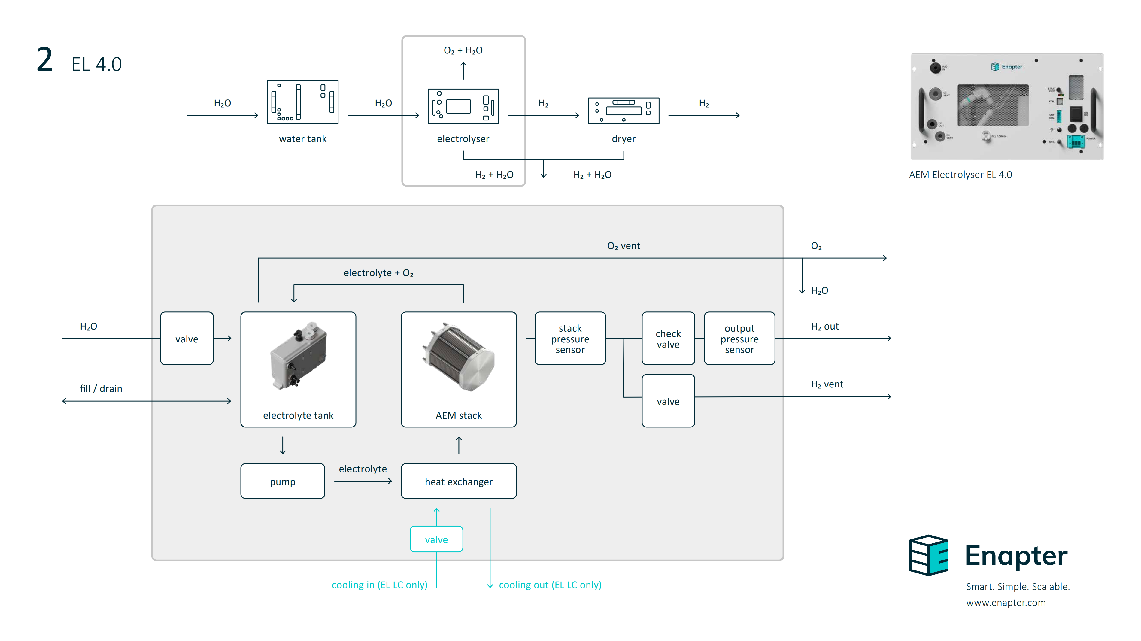
Our plug & play AEM electrolysers turn renewable electricity and water into low-cost green hydrogen. At any scale, for any application.

# 📖 Downloads
| Datasheet | Owner’s Manual | Battery Limits | Quick Start Guides | Comparison with EL 2.1 | Types of EL 4.0 | Cooling | Power Supply | Certification | |
|---|---|---|---|---|---|---|---|---|---|
| PDF EN | Air cooled | AC | CE Certificate | ||||||
| DC | |||||||||
| Liquid cooled | AC | CE Certificate | |||||||
| DC |
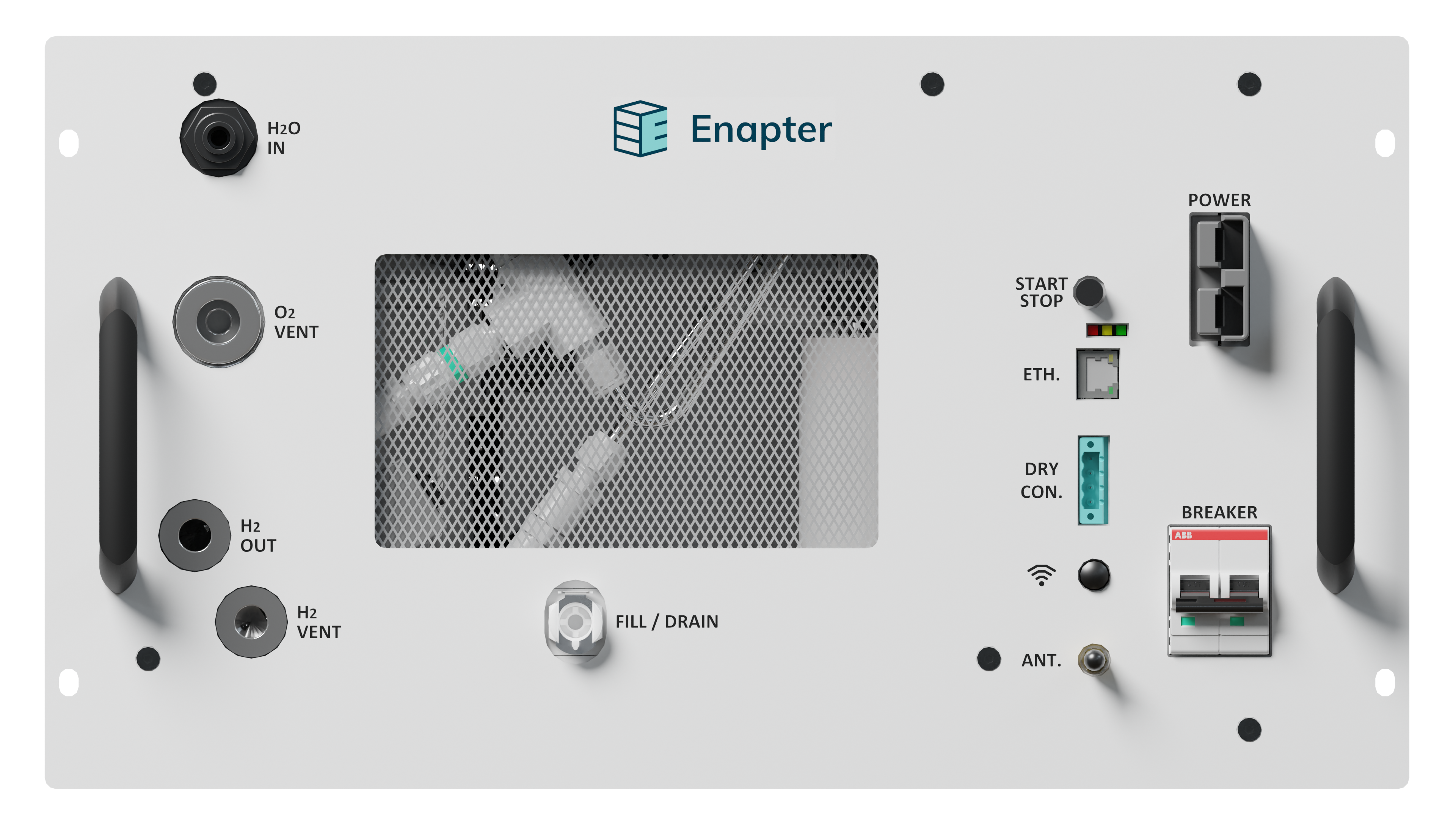
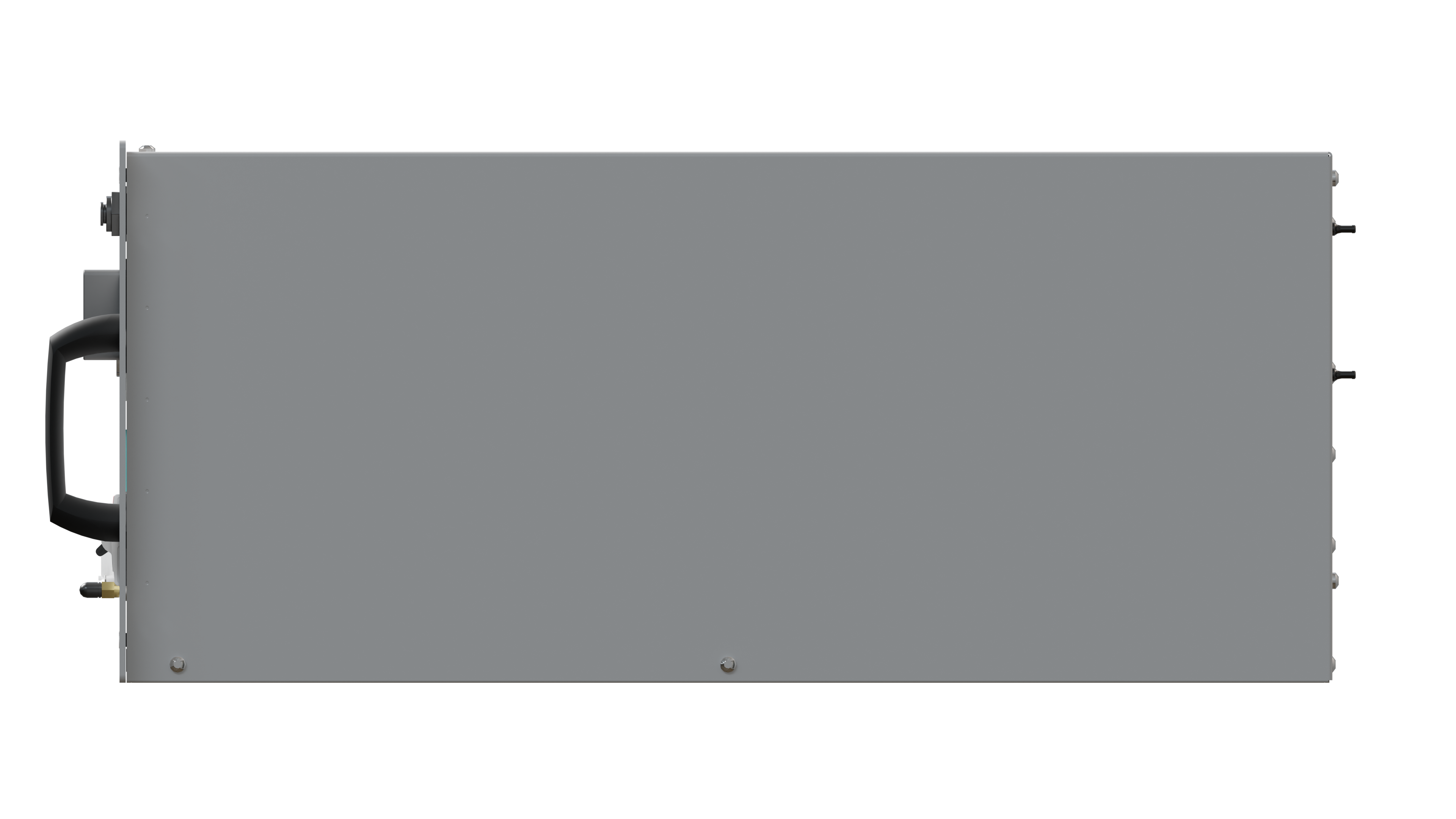
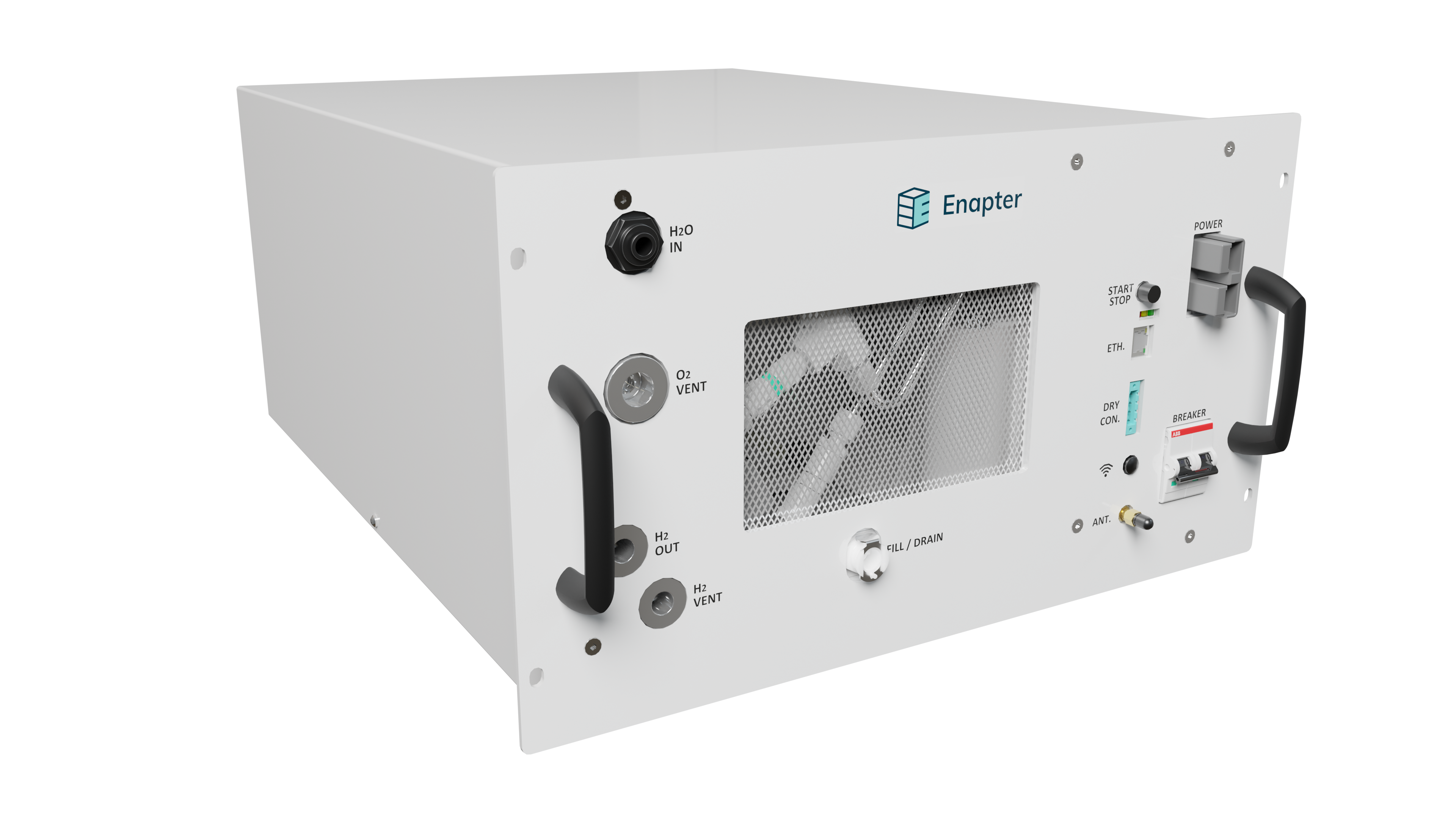
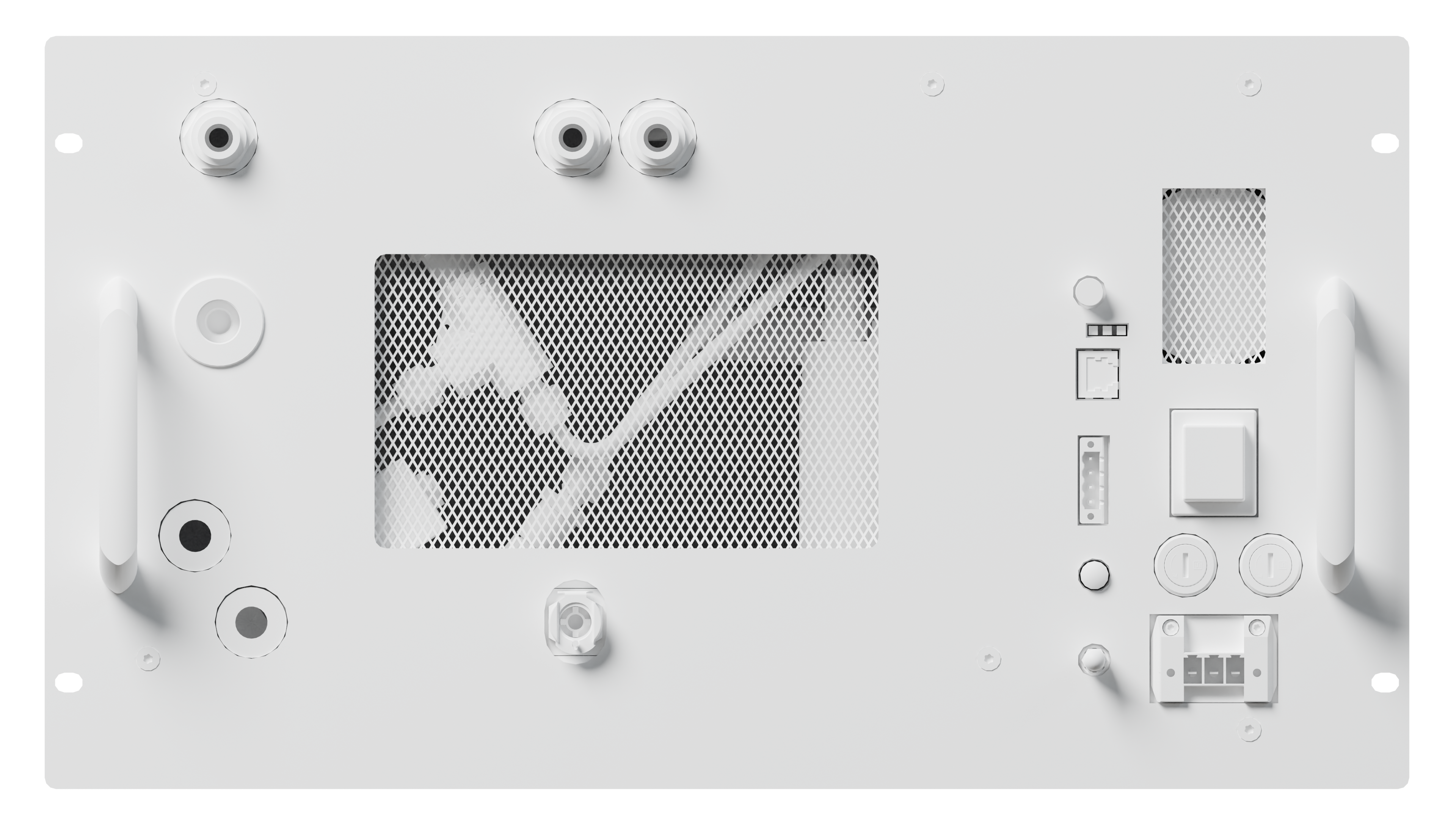
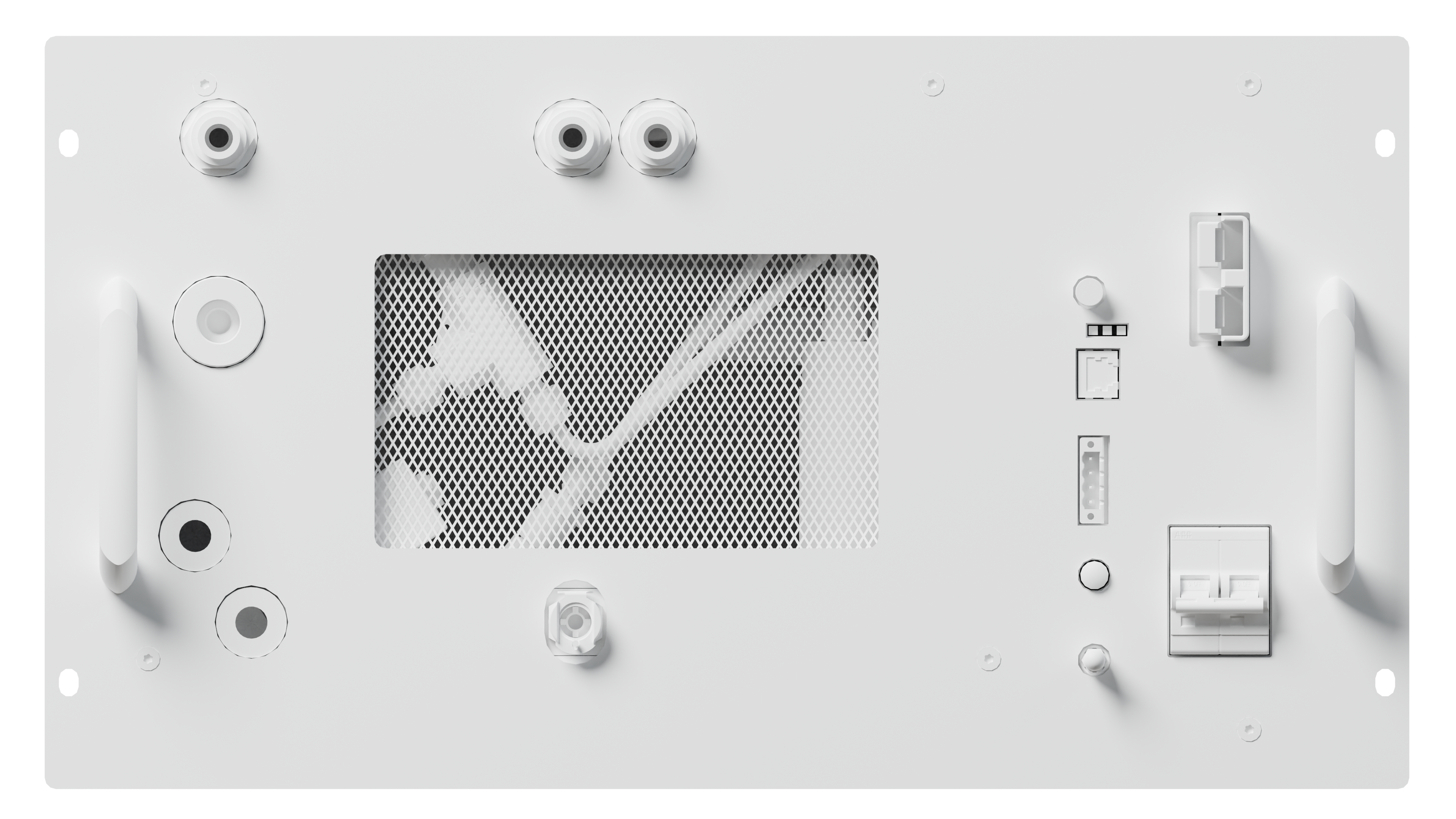
# 📸 Images
| Simplified Schematic Overview | CAD Drawings | Dimensions | Front | Isometric | Side | Perspective | |
|---|---|---|---|---|---|---|---|
| PNG | 3D STP 3D IGS | Download | Download | Download | Download | ||
| 3D STP 3D IGS | Download | Download | Download | Download | |||
| 3D STP 3D IGS | Download | Download | Download | ||||
| 3D STP 3D IGS | Download | Download | Download |
# 🚀 Getting Started
Installing electrolyser for the first time? Download Quick Start Guide and follow instructions.

Note
Electrolyser EL 4.0 installation process requires Enapter Mobile App (opens new window) or Web GUI (opens new window).
# 🖥️ Web GUI
Enapter Electrolyser Web GUI (Graphical User Interface) made for local control and monitoring using a web browser. For more information please check Web GUI Documentation (opens new window).

# ☁️ Cloud over Ethernet Beta
Warning
Cloud over Ethernet is in Beta.
Cloud over Ethernet is a cutting-edge feature for Enapter Web GUI that empowers Enapter electrolyser users to seamlessly connect their devices to cloud services using an Ethernet interface. This advanced connectivity solution opens up a realm of possibilities for remote monitoring, data logging, and control of the electrolyser through a secure and efficient cloud platform.
For more information please check Cloud over Ethernet (opens new window) documentation.
# 📟 HMI App
Enapter HMI app (human machine inetrface) made for local control and monitoring all electrolysers on site using a tablet or computer. No internet or cable connection needed, the app will discover and connect to all devices in local network automatically. For more information please check HMI App Documentation (opens new window).

# 🚦 Status Indications
# LEDs Indications
| Action | Description | LED | |
|---|---|---|---|
 | Power on | The device will turn on as soon as the required input voltage is supplied to the EL 4.0 and perform a startup self-check. | Red, yellow & green blink thrice |
 | Stand-by (Idle state) | The device is idle, waiting for the start of production. | Red, yellow & green are off |
 | Stand-by (Max pressure state) | The device reached maximum pressure (normally 35 bar) and will resume hydrogen production automatically when the restart output pressure setpoint is reached. | Green blinking |
 | Steady | The device in steady state. | Green steady |
 | Button press | When the start-stop button is pressed. | Red, yellow & green blink once |
 | Factory Settings Reset | Simultaneously pressing the start-stop button and powering up the device will activate Factory Settings Reset. | Running fire (each LED blinks after another) |
 | Maintenance mode | The device is in maintenance mode. | Yellow steady |
 | Locate device | When locate device is enabled via remote control. | Red, yellow & green blinking |
 | Warning | Heads-up event which should be taken into account to avoid Error or Fatal Error. | Yellow Blinks |
 | Error | System Stopped. Recoverable error. | Red Blinks |
 | Fatal Error | System stopped. Unrecoverable error. Hardware repair required. Please contact Enapter support. | Red and Yellow Blinks |
  | Panic | System stopped. Unrecoverable error. Please contact Enapter support. | Red steady with green steady (hardware problem) or yellow steady (software problem) |
# Sound Indications
Safety Board has built in buzzer which helps to provide additional level of information for user.
| Action | Description | Sound |
|---|---|---|
| Buzzer is broken or board is not operational. | Silence on start | |
| Successful Safety Board Start. Buzzer is functional. | Short Beep | |
| Successful Factory Settings Reset. | Three Short Beeps | |
| Safety Fatal Error FY_51 | SIF1: Hydrogen stack overpressure | Long Beep - Pause - Short Beep |
| Safety Fatal Error FY_52 | SIF2: Recombiner chamber overtemperature | Long Beep - Pause - Two Short Beeps |
| Safety Fatal Error FY_53 | SIF3: Water leakage detection | Long Beep - Pause - Three Short Beeps |
| Safety Fatal Error FY_54 | SIF4: Tank overpressure | Long Beep - Pause - Four Short Beeps |
| Safety Fatal Error FY_55 | SIF5: Dilution fan for hydrogen concentration | Long Beep - Pause - Five Short Beeps |
| Safety Fatal Error FY_56 | SIF6: Safety Electronic Board temperature | Long Beep - Pause - Six Short Beeps |
| Safety Fatal Error FY_20 | Dry contact | Long Beep - Pause - Seven Short Beeps |
| Safety Fatal Error FY_21 | Communication fail | Long Beep - Pause - Eight Short Beeps |
| Safety Fatal Error FY_22 | Safe State requested by Control Board | Long Beep - Pause - Nine Short Beeps |
| Safety Fatal Error FY_23 | Incompatible Control Board version | Long Beep - Pause - Ten Short Beeps |
| Safety Fatal Error FY_24 | Relay broken | Long Beep - Pause - 11 Short Beeps |
| Safety Fatal Error FY_25 | Proof-test can not be started | Long Beep - Pause - 12 Short Beeps |
| Safety Fatal Error FY_26 | Proof-test failed | Long Beep - Pause - 13 Short Beeps |
| Safety Fatal Error FY_27 | Inner pressure transmitter broken | Long Beep - Pause - 14 Short Beeps |
| Safety Fatal Error FY_28 | Wrong Control Board | Long Beep - Pause - 16 Short Beeps |
| Safety Fatal Error FY_29 | Recombiner Chamber Temperature Sensor broken | Long Beep - Pause - 17 Short Beeps |
| Safety Fatal Error FY_30 | Tachometer or Fan broken | Long Beep - Pause - 18 Short Beeps |
| Safety Fatal Error FY_31 | Safety Board Temperature Sensor broken | Long Beep - Pause - 19 Short Beeps |
| Safety Fatal Error FY_33 | Brownout | Long Beep - Pause - 20 Short Beeps |
| Dry Contact restored | Normal operation restored | Long Beep |
| Unexpected Error | Used in cases when it is not possible to understand the root cause and ensure delivery of error code in communication packet. | SOS: 3 Short Beeps - 3 Long Beeps - 3 Short Beeps |
| Safety Fatal Error FY_21 | Indicates communication lost with Control Board. NOTE: COMMUNICATION FAIL is normal when Control Board firmware updated. It loses communication and identifies the update process when you are not allowed to turn off the power. | Consecutive Beeps |
# ⚠️ Events
# Severity Levels
| Code | Severity Level | LED Indication | Description | Comment |
|---|---|---|---|---|
| F | Fatal Error | Red and Yellow Blinks | System stopped. Unrecoverable error. Hardware repair required. | e.g. Pressure sensor is not connected or broken. |
| E | Error | Red Blinks | System Stopped. Recoverable error. | e.g. No input water pressure and internal water tank is empty. |
| W | Warning | Yellow Blinks | Heads-up event which should be taken into account to avoid Error or Fatal Error. | e.g. No input water pressure and internal water tank is full. |
# Routines
| Code | Routine | Comment |
|---|---|---|
| P | Platform | |
| C | Electrolyte Pump | |
| D | Stack Ramp Down | |
| R | Water Refilling | |
| S | Steady Hydrogen Production | |
| T | Electrolyte Heater | |
| U | Stack Ramp Up | |
| X | Safety Check | |
| F | Anti-freezing | |
| L | Leakage Test | |
| O | Blowdown | |
| H | Heartbeat | |
| Z | Polarization Curve | |
| Y | Safety Board |
# Warning, Error and Fatal Error Codes
Note
The Code and Name marked in bold are introduced in the current release of firmware.
| Code | Name | Component | Display Name | Description | |
|---|---|---|---|---|---|
| 0x0FFF |
internal
| Internal error | Please contact Enapter Customer Support. System failed with an unexpected error. | ||
| 0x360A |
WH_10
Severity W
/
Routine H |
| Lost Modbus safety heartbeat communication | Modbus communication between the Electrolyser and the Modbus master device has been lost. Please check that the Ethernet cable is properly installed, the connection is established, and the Modbus master is operational. | |
| 0x360B |
WH_11
Severity W
/
Routine H |
| Lost Enapter Gateway safety heartbeat communication | Communication between the Electrolyser and the Enapter Gateway has been lost. Please check that the Wi-Fi connection is stable and ensure that the Gateway is operational. | |
| 0x360C |
WH_12
Severity W
/
Routine H | UCM | Lost UCM communication | Lost communication between the Control Board and the UCM (Universal Communication Module). Please contact Enapter Customer Support. | |
| 0x358A |
WO_10
Severity W
/
Routine O | PT101C | Outer hydrogen pressure is too high for blowdown | Please lower the outer hydrogen pressure below 25 bar in order to start the blowdown routine. | |
| 0x3594 |
WO_20
Severity W
/
Routine O | Blowdown routine is active | The blowdown procedure will start once hydrogen production starts. Please ensure that the Hydrogen Purge line is correctly connected and routed to a safe area. | ||
| 0x159E |
FO_30
Severity F
/
Routine O |
| Hydrogen Purge line obstruction or blowdown failure | The Hydrogen Purge line is obstructed or the adjustable check valve (CV101B) cracking pressure is set incorrectly. Please verify that the Hydrogen Purge line is unobstructed, enable Blowdown for the next hydrogen production cycle, and reset the system. Please contact Enapter Customer Support. | |
| 0x318A |
WR_10
Severity W
/
Routine R | PT105 | Water inlet pressure is too high | Water inlet pressure has exceeded 4 barg. The automatic refilling will not work. | |
| 0x3194 |
WR_20
Severity W
/
Routine R | PT105 | Water inlet pressure is too low | Insufficient water inlet pressure. The automatic refilling will not work. | |
| 0x3195 |
WR_21
Severity W
/
Routine R | Refilling timeout | Make sure that the water inlet requirements are met and power cycle the device. | ||
| 0x330A |
WU_10
Severity W
/
Routine U | PT101A | Gas-side pressure is not atmospheric | Hydrogen Vent (Hydrogen Purge) line pressure detected. Ramp-up is not possible. Please check that the Hydrogen Vent (Hydrogen Purge) line is not obstructed. | |
| 0x2314 |
EU_20
Severity E
/
Routine U | none | Target current could not be reached. | Please stop the hydrogen production immediately, switch the device into maintenance mode, drain the electrolyte and fill up the device with fresh electrolyte. Please check the water input quality fulfills the conductivity requirements and consider a change of purification cartridges. | |
| 0x3215 |
WS_21
Severity W
/
Routine S | PT101A | Drift in inner hydrogen pressure sensor | Please contact Enapter Customer Support. Inner hydrogen pressure mismatch has been detected. | |
| 0x3294 |
WT_20
Severity W
/
Routine T | F103A | Electrolyte cooling fan broken | Please contact Enapter Customer Support. The electrolyte cooling fan must be checked. | |
| 0x3432 |
WX_50
Severity W
/
Routine X | PT101A | Inner hydrogen pressure check disabled | Please contact Enapter Customer Support. Safety routine check for inner hydrogen pressure is disabled. | |
| 0x3433 |
WX_51
Severity W
/
Routine X | WPS104 | Water presence check disabled | Please contact Enapter Customer Support. Safety routine check for water presence is disabled. | |
| 0x3434 |
WX_52
Severity W
/
Routine X | 48V PSU | Power supply unit check is disabled | Please contact Enapter Customer Support. Safety routine check for the power supply unit is disabled. | |
| 0x3435 |
WX_53
Severity W
/
Routine X | HASS | Stack current check disabled | Please contact Enapter Customer Support. Safety routine check for the stack current is disabled. | |
| 0x3436 |
WX_54
Severity W
/
Routine X | TSH106 | Electrolyte backflow temperature check disabled | Please contact Enapter Customer Support. Safety routine check for the electrolyte backflow temperature is disabled. | |
| 0x3437 |
WX_55
Severity W
/
Routine X | TS108 | Control board temperature check disabled | Please contact Enapter Customer Support. Safety routine check for the control board temperature is disabled. | |
| 0x3438 |
WX_56
Severity W
/
Routine X | PSH102 | Electrolyte tank pressure check disabled | Please contact Enapter Customer Support. Safety routine check for the electrolyte tank pressure is disabled. | |
| 0x3439 |
WX_57
Severity W
/
Routine X | TSLL102B | Low electrolyte temperature check disabled | Please contact Enapter Customer Support. Safety routine check for the low electrolyte temperature is disabled. | |
| 0x343A |
WX_58
Severity W
/
Routine X | PSHH102B | Inner overpressure check disabled | Please contact Enapter Customer Support. Safety routine check for high inner hydrogen pressure is disabled. | |
| 0x343B |
WX_59
Severity W
/
Routine X | PT105 | Water inlet pressure check disabled | Please contact Enapter Customer Support. Safety routine check for the inlet pressure (PT105) is disabled. | |
| 0x343C |
WX_60
Severity W
/
Routine X | TT102A | Electrolyte tank temperature check disabled | Please contact Enapter Customer Support. Safety routine check for the electrolyte tank temperature is disabled. | |
| 0x343D |
WX_61
Severity W
/
Routine X | FM106 | Electrolyte flow meter check disabled | Please contact Enapter Customer Support. Safety routine check for the electrolyte flow meter (FM106) is disabled. | |
| 0x343E |
WX_62
Severity W
/
Routine X | F103A | Electrolyte cooling fan check disabled | Please contact Enapter Customer Support. Safety routine check for the electrolyte cooling fan is disabled. | |
| 0x343F |
WX_63
Severity W
/
Routine X | TT106 | Electrolyte backflow temperature check disabled | Please contact Enapter Customer Support. Safety routine check for the electrolyte backflow temperature is disabled. | |
| 0x3440 |
WX_64
Severity W
/
Routine X | PT101C | Outer hydrogen pressure check disabled | Please contact Enapter Customer Support. Safety routine check for the outer hydrogen pressure is disabled. | |
| 0x3441 |
WX_65
Severity W
/
Routine X | F104B | Chassis circulation fan check disabled | Please contact Enapter Customer Support. Safety routine check for the chassis circulation fan is disabled. | |
| 0x3442 |
WX_66
Severity W
/
Routine X | F108C | Electronic compartment cooling fan check disabled | Please contact Enapter Customer Support. Safety routine check for the electronic compartment cooling fan is disabled. | |
| 0x3443 |
WX_67
Severity W
/
Routine X | Dry contact | Dry contact check disabled | Please contact Enapter Customer Support. Safety routine check for the dry contact is disabled. External dry signal will be ignored. | |
| 0x3445 |
WX_69
Severity W
/
Routine X | MCU Temperature Sensor | Control Board temperature check disabled | Please contact Enapter Customer Support. Safety routine check for the Control Board temperature is disabled. | |
| 0x228A |
ET_10
Severity E
/
Routine T | TT102A | Electrolyte temperature is too low | Please make sure that the room temperature is at least 6°C. Keep the EL powered to ensure that the heating routine continues to protect the device internals. | |
| 0x108A |
FC_10
Severity F
/
Routine C | P107 | Pump broken | Please contact Enapter Customer Support. The electrolyte pump may be broken. | |
| 0x128A |
FT_10
Severity F
/
Routine T | TT106 | Electrolyte temperature is too high | Please make sure that the air ventilation is not obstructed or the liquid cooling loop is operating properly as well as the ambient temperature does not exceed the device specifications. If the error persists, please contact Enapter Customer Support. | |
| 0x118A |
FR_10
Severity F
/
Routine R | LSHH102A | Electrolyte level is too high | Electrolyte level is too high. Please interrupt the water supply to the system and contact Enapter Customer Support. | |
| 0x1194 |
FR_20
Severity F
/
Routine R | LSL102D | Electrolyte level is too low | Please switch the Electrolyser into maintenance mode, drain it fully, and then fill the electrolyte tank with fresh electrolyte solution. | |
| 0x11B2 |
FR_50
Severity F
/
Routine R |
| Conflict between water level sensors (low and medium) | Please contact Enapter Customer Support. Internal water sensors may be stuck (conflict between low and medium levels). | |
| 0x11B3 |
FR_51
Severity F
/
Routine R |
| Conflict between water level sensors (medium and high) | Please contact Enapter Customer Support. Internal water sensors may be stuck (conflict between medium and high levels). | |
| 0x11B4 |
FR_52
Severity F
/
Routine R |
| Conflict between water level sensors (high and very high) | Please contact Enapter Customer Support. Internal water sensors may be stuck (conflict between high and very high levels). | |
| 0x11A8 |
FR_40
Severity F
/
Routine R | Refilling unsuccessful | Please contact Enapter Customer Support. Refilling was unsuccessful. | ||
| 0x1501 |
FL_01
Severity F
/
Routine L | Inner hydrogen pressure reading is below the expected value | Please contact Enapter Customer Support. Pressure readings are below nominal values. The device needs to be checked or repaired. | ||
| 0x1114 |
FD_20
Severity F
/
Routine D | PT101A | Inner hydrogen pressure reading is below the expected value | Please contact Enapter Customer Support. The inner hydrogen pressure transmitter detected a non-nominal pressure drop during the ramp down leakage test. | |
| 0x348A |
WF_10
Severity W
/
Routine F | Electrolyte anti-freeze routine is disabled | Electrolyte anti-freeze routine has been disabled due to its component failure. | ||
| 0x148A |
FF_10
Severity F
/
Routine F | Frozen pipes | Please contact Enapter Customer Support. Electrolyte flow is outside pump control limits. | ||
| 0x2401 |
EX_01
Severity E
/
Routine X | PT101A | Inner hydrogen pressure is too high | Please contact Enapter Customer Support. The inner hydrogen pressure has exceeded 37 (or 9) barg (nominal, but high). | |
| 0x1402 |
FX_02
Severity F
/
Routine X | WPS104 | Water presence detected | Please contact Enapter Customer Support. Water is leaking inside the Electrolyser. Please remove the water supply and power from the system and drain immediately. | |
| 0x1403 |
FX_03
Severity F
/
Routine X | 48V PSU | PSU broken | Please contact Enapter Customer Support. PSU failure detected. No voltage on stack. | |
| 0x1404 |
FX_04
Severity F
/
Routine X | HASS | Stack current is too high | Please contact Enapter Customer Support. Stack overcurrent detected. | |
| 0x1405 |
FX_05
Severity F
/
Routine X | TSH106 | Backflow temperature is too high | Please contact Enapter Customer Support. The stack outlet temperature is too high. | |
| 0x1407 |
FX_07
Severity F
/
Routine X | TS108 | Control board temperature is too high | The control board temperature is too high. Please check and clean air ventilation holes. If the error persists, contact Enapter Customer Support. | |
| 0x1408 |
FX_08
Severity F
/
Routine X | PSH102 | Electrolyte tank pressure is too high | Please make sure that the Oxygen Vent line is not blocked. | |
| 0x1409 |
FX_09
Severity F
/
Routine X | TSLL102B | Electrolyte temperature is too low | Please make sure that the ambient temperature is at least 6°C. Keep the Electrolyser powered to ensure the heating routine continues to protect the device internals. | |
| 0x140A |
FX_10
Severity F
/
Routine X |
| Hydrogen pressure is too high | Please contact Enapter Customer Support. The pressure transmitter calibration needs to be verified. | |
| 0x140B |
FX_11
Severity F
/
Routine X | MCU Temperature Sensor | Control Board MCU temperature is too high | Please make sure that the ambient temperature is below 45°C. | |
| 0x140C |
FX_12
Severity F
/
Routine X | PT101C | Outer hydrogen pressure is too high | Please contact Enapter Customer Support. The calibration of the pressure transmitter needs to be verified. | |
| 0x141E |
FX_30
Severity F
/
Routine X | PT105 | Water inlet pressure transmitter broken | Please contact Enapter Customer Support. The water inlet pressure cannot be measured. | |
| 0x141F |
FX_31
Severity F
/
Routine X | TT102A | Electrolyte tank temperature transmitter broken | Please contact Enapter Customer Support. The temperature of the electrolyte tank cannot be measured. | |
| 0x1420 |
FX_32
Severity F
/
Routine X | FM106 | Electrolyte flow meter broken | Please contact Enapter Customer Support. The electrolyte flow cannot be measured. | |
| 0x1421 |
FX_33
Severity F
/
Routine X | TT106 | Electrolyte backflow temperature transmitter broken | Please contact Enapter Customer Support. The temperature of the electrolyte backflow cannot be measured. | |
| 0x1422 |
FX_34
Severity F
/
Routine X | PT101A | Inner hydrogen pressure transmitter broken | Please contact Enapter Customer Support. The inner hydrogen pressure cannot be measured. | |
| 0x1423 |
FX_35
Severity F
/
Routine X | PT101C | Outer hydrogen pressure transmitter broken | Please contact Enapter Customer Support. The outer hydrogen pressure cannot be measured. | |
| 0x1424 |
FX_36
Severity F
/
Routine X | F108B | Chassis circulation fan broken | Please contact Enapter Customer Support. The chassis air circulation fan speed cannot be measured. | |
| 0x1425 |
FX_37
Severity F
/
Routine X | F108C | Electronic compartment cooling fan broken | Please contact Enapter Customer Support. The speed of the electronic compartment cooling fan cannot be measured. | |
| 0x1426 |
FX_38
Severity F
/
Routine X | TS108 | Electronic board temperature transmitter broken | Please contact Enapter Customer Support. The temperature of the electronic board cannot be measured. | |
| 0x1427 |
FX_39
Severity F
/
Routine X | HASS | Stack current sensor broken | Please contact Enapter Customer Support. The stack current cannot be measured. | |
| 0x1428 |
FX_40
Severity F
/
Routine X | External circuit or switch | Dry contact triggered | Dry contact triggered system stop. Please check your control system to understand what triggered the dry contact. | |
| 0x3F85 |
WP_05
Severity W
/
Routine P | CR2032 battery on control board | Low battery voltage | Please contact Enapter Customer Support. Main board battery charge is too low. | |
| 0x1201 |
FS_01
Severity F
/
Routine S | 48V PSU | Broken PSU | Please contact Enapter Customer Support. PSU might be broken. | |
| 0x120A |
FS_10
Severity F
/
Routine S |
| Broken membrane | Please contact Enapter Customer Support. Stack membrane might be broken. | |
| 0x31B5 |
WR_53
Severity W
/
Routine R | LSHH102A | Drain to high level | Electrolyte level is above the high level (overfilling), please drain to the high level. | |
| 0x321E |
WS_30
Severity W
/
Routine S | Elevated stack voltage | The stack voltage is elevated. Please verify your input water quality and perform maintenance if necessary. We recommend operating at lower production rates to extend stack lifetime and temporarily stopping the production of H2 with this system to allow for voltage recovery. | ||
| 0x1F86 |
FP_06
Severity F
/
Routine P | Control board MCU | Insufficient resources for DCN/IDCN | Please contact Enapter Customer Support. There are not enough hardware resources available to enable DCN/IDCN support. | |
| 0x3F8A |
WP_10
Severity W
/
Routine P | Platform Factory Reset Incomplete | Please check manual (see Factory Settings Reset and Troubleshooting sections) | ||
| 0x3F8E |
WP_14
Severity W
/
Routine P | System Factory Reset Incomplete | Please check manual (see Factory Settings Reset and Troubleshooting sections) | ||
| 0x3F90 |
WP_16
Severity W
/
Routine P | Safety Factory Reset Incomplete | Please check manual (see Factory Settings Reset and Troubleshooting sections) | ||
| 0x3F92 |
WP_18
Severity W
/
Routine P | Communication Factory Reset Incomplete | Please check manual (see Factory Settings Reset and Troubleshooting sections) | ||
| 0x3F93 |
WP_19
Severity W
/
Routine P | Reserved Factory Reset Warning | This code is reserved for future use. | ||
| 0x178A |
FY_10
Severity F
/
Routine Y | Safety Board | INVALID COMMUNICATION PACKET | Control Board received an invalid communication packet from the Safety Board. The system is now in the Safe State and cannot be operated. To remove the error, power cycle the device. If the error persists, contact Enapter Customer Support. | |
| 0x1794 |
FY_20
Severity F
/
Routine Y | Safety Board | DRY CONTACT | Safety Board DRY CONTACT opened. The system is now in the Safe State and cannot be operated. Please check the DRY CONTACT safety loop circuit and fix it if necessary. The error will be resolved as soon as the DRY CONTACT is closed and the device is reset. | |
| 0x1795 |
FY_21
Severity F
/
Routine Y | Safety Board | COMMUNICATION FAILURE | Safety Board experienced communication issues with the Control Board. The system is now in the Safe State and cannot be operated. Power cycle the device to remove the error. If the error persists, contact Enapter Customer Support. | |
| 0x1796 |
FY_22
Severity F
/
Routine Y | Safety Board | SAFE STATE REQUESTED BY CONTROL BOARD | Control Board requested transition into Safe State. The system is now in the Safe State and cannot be operated. Power cycle the device to resolve the issue. If the error persists, contact Enapter Customer Support. | |
| 0x1797 |
FY_23
Severity F
/
Routine Y | Safety Board | INCOMPATIBLE CONTROL BOARD VERSION | Please contact Enapter Customer Support. Safety Board hardware or software is incompatible with Control Board hardware or software. The system is now in the Safe State and cannot be operated. | |
| 0x1798 |
FY_24
Severity F
/
Routine Y | Safety Board | RELAY BROKEN | Please contact Enapter Customer Support. Safety Board safety relay does not pass self-diagnostics. The system is now in the Safe State and cannot be operated. | |
| 0x1799 |
FY_25
Severity F
/
Routine Y | Safety Board | PROOF-TEST CANNOT BE STARTED | The proof-test function was requested while the Electrolyser was not in Idle Mode. The system is now in the Safe State and cannot be operated. If the error persists, contact Enapter Customer Support. | |
| 0x179A |
FY_26
Severity F
/
Routine Y | Safety Board | PROOF-TEST FAILED | The requested proof-test function failed. The system is now in the Safe State and cannot be operated. If the error persists, please contact Enapter Customer Support. | |
| 0x179B |
FY_27
Severity F
/
Routine Y | Safety Board | INNER HYDROGEN PRESSURE TRANSMITTER BROKEN | Please contact Enapter Customer Support. Inner hydrogen pressure transmitter is broken. The system is now in the Safe State and cannot be operated. | |
| 0x179C |
FY_28
Severity F
/
Routine Y | Safety Board | INCORRECT CONTROL BOARD | Please contact Enapter Customer Support. Safety Board is connected to the wrong Control Board. The system is now in the Safe State and cannot be operated. | |
| 0x179D |
FY_29
Severity F
/
Routine Y | Safety Board | RECOMBINER CHAMBER TEMPERATURE SENSOR BROKEN | Please contact Enapter Customer Support. Recombiner chamber temperature sensor is broken. The system is now in the Safe State and cannot be operated. | |
| 0x179E |
FY_30
Severity F
/
Routine Y | Safety Board | TACHOMETER OR FAN BROKEN | Please contact Enapter Customer Support. Tachometer and/or fan are broken. The system is now in the Safe State and cannot be operated. | |
| 0x179F |
FY_31
Severity F
/
Routine Y | Safety Board | SAFETY BOARD TEMPERATURE SENSOR BROKEN | Please contact Enapter Customer Support. Safety Board temperature sensor is broken. The system is now in the Safe State and cannot be operated. | |
| 0x17A0 |
FY_32
Severity F
/
Routine Y | Safety Board | CONTROL BOARD AND SAFETY BOARD PAIRED | Safety Board successfully paired with Control Board. If you see this error for the first time, power cycle the device to resolve it. If the error persists, contact Enapter R&D Team. | |
| 0x37B2 |
WY_50
Severity W
/
Routine Y | Safety Board | SIF-test has been started | Electrolyser runs the SIF-test and the system transitions into corresponding error state | |
| 0x17B3 |
FY_51
Severity F
/
Routine Y | Safety Board | SIF1: HYDROGEN STACK OVERPRESSURE | Safety Board detected overpressure in the hydrogen stack. The system is now in the Safe State and cannot be operated. Please contact Enapter Customer Support. | |
| 0x17B4 |
FY_52
Severity F
/
Routine Y | Safety Board | SIF2: RECOMBINER CHAMBER OVERTEMPERATURE | Safety Board detected overtemperature in the recombiner chamber. The system is now in the Safe State and cannot be operated. Please contact Enapter Customer Support. | |
| 0x17B5 |
FY_53
Severity F
/
Routine Y | Safety Board | SIF3: WATER LEAKAGE DETECTION | Safety Board detected water leakage inside the Electrolyser. The system is now in the Safe State and cannot be operated. Please contact Enapter Customer Support. | |
| 0x17B6 |
FY_54
Severity F
/
Routine Y | Safety Board | SIF4: TANK OVERPRESSURE | Safety Board detected an overpressure in the process electrolyte tank. The system is now in the Safe State and cannot be operated. Please contact Enapter Customer Support. | |
| 0x17B7 |
FY_55
Severity F
/
Routine Y | Safety Board | SIF5: DILUTION FAN FOR HYDROGEN CONCENTRATION | Safety Board detected a malfunction of the dilution fan. The system is now in the Safe State and cannot be operated. Please contact Enapter Customer Support. | |
| 0x17B8 |
FY_56
Severity F
/
Routine Y | Safety Board | SIF6: SAFETY ELECTRONIC BOARD TEMPERATURE | Safety Board detected overtemperature of the PCB. The system is now in the Safe State and cannot be operated. Please contact Enapter Customer Support. | |
| 0x3295 |
WT_21
Severity W
/
Routine T | TT102A | Slow electrolyte heating | Electrolyte temperature is not increasing as expected. Please check the environmental conditions and contact Enapter Customer Support if the warning persists. | |
| 0x330B |
WU_11
Severity W
/
Routine U | LSM102C | Electrolyte level insufficient for start-up | Heater cannot be started due to insufficient electrolyte level in the internal electrolyte tank. Refill the electrolyte, reset the system, and try again. | |
| 0x130C |
FU_12
Severity F
/
Routine U |
| Insufficient stack current | Stack voltage limitation blocks reaching the specified current. Please contact Enapter Customer Support. | |
| 0x1314 |
FU_20
Severity F
/
Routine U | PT101A | Ramp-up leak check failed | Inner hydrogen pressure decreased too quickly during ramp-up leak check. Please contact Enapter Customer Support. | |
| 0x120B |
FS_11
Severity F
/
Routine S | PT101A | Steady-state leak check failed | Stack pressurization is too slow during steady-state leak check. Please contact Enapter Customer Support. | |
| 0x120C |
FS_12
Severity F
/
Routine S |
| Insufficient stack current | Stack voltage limitation blocks reaching the specified current. Please contact Enapter Customer Support. | |
| 0x1F81 |
FP_01
Severity F
/
Routine P | Brownout detected | System detected a brownout. Please restore power and reset the system. | ||
| 0x1F82 |
FP_02
Severity F
/
Routine P | New configuration parameters added | Please contact Enapter Customer Support to configure the new system parameters. | ||
| 0x1F83 |
FP_03
Severity F
/
Routine P | Broken periphery | Please contact Enapter Customer Support. An unexpected error has occurred. | ||
| 0x3F84 |
WP_04
Severity W
/
Routine P | Stuck power button | Power button was pressed for too long. Please release the button. | ||
| 0x3196 |
WR_22
Severity W
/
Routine R | Refilling failure | Refilling has failed. Please check your water supply system. | ||
| 0x3197 |
WR_23
Severity W
/
Routine R | Draining timeout | Make sure that the water draining requirements are met and power cycle the device. | ||
| 0x319E |
WR_30
Severity W
/
Routine R | Electrolyte is too old | The quality of the electrolyte has deteriorated over time degradation. Replace the electrolyte. If the error persists, contact Enapter Customer Support. | ||
| 0x31B3 |
WR_51
Severity W
/
Routine R | Drain completely | Electrolyte level is below the minimum. The Electrolyser is ready to be refilled. | ||
| 0x31B4 |
WR_52
Severity W
/
Routine R | Refill to high level | Continue filling the electrolyte until it reaches the high level. | ||
| 0x31B6 |
WR_54
Severity W
/
Routine R | Refill to medium level | Please keep refilling until electrolyte reaches the medium level. | ||
| 0x3216 |
WS_22
Severity W
/
Routine S | Refilling is not occurring | Please check the water supply. If not fixed soon, hydrogen production will stop. | ||
| 0x321F |
WS_31
Severity W
/
Routine S | Derating due to temperature | The current on the stack has been reduced to prevent the electrolyte from overheating. Please contact Enapter Customer Support. | ||
| 0x3220 |
WS_32
Severity W
/
Routine S | Derating due to voltage | The current on the stack has been reduced to prevent the stack from over voltage. Please contact Enapter Customer Support. | ||
| 0x3221 |
WS_33
Severity W
/
Routine S | The electrolyser has been inactive for a long time | Electrolyte requires change due to extended non-operative system conditions. Please swap the electrolyte and run the system when able. | ||
| 0x140D |
FX_13
Severity F
/
Routine X | High hydrogen presence detected | High levels of hydrogen have been detected. Please contact Enapter Customer Support. | ||
| 0x1429 |
FX_41
Severity F
/
Routine X | Water level sensor broken | Please contact Enapter Customer Support. The water level sensor is broken. | ||
| 0x142A |
FX_42
Severity F
/
Routine X | Common trip | Please contact Enapter Customer Support. An error has been received from the Safety Board. | ||
| 0x142B |
FX_43
Severity F
/
Routine X | Insufficient electrolyte flow | Pump broken or insufficient electrolyte flow during hydrogen production. Please check the electrolyte. | ||
| 0x142C |
FX_44
Severity F
/
Routine X | Hydrogen sensor broken | Please contact Enapter Customer Support. The H2 concentration in air cannot be measured. | ||
| 0x340E |
WX_14
Severity W
/
Routine X | Hydrogen presence detected | Hydrogen presence detected inside the Electrolyser. Please contact Enapter Customer Support. | ||
| 0x340F |
WX_15
Severity W
/
Routine X | Hydrogen sensor regeneration | Please contact Enapter Customer Support. | ||
| 0x3410 |
WX_16
Severity W
/
Routine X |
| Electrolyte large temperature discrepancy | Electrolyte large temperature discrepancy between flow and backflow. If the error persists, please contact Enapter Customer Support. | |
| 0x3444 |
WX_68
Severity W
/
Routine X | Water level check disabled | Please contact Enapter Customer Support. Water level check is disabled. | ||
| 0x3446 |
WX_70
Severity W
/
Routine X | Hydrogen sensor check disabled | Please contact Enapter Customer Support. Hydrogen sensor check is disabled. | ||
| 0x3447 |
WX_71
Severity W
/
Routine X | Electrolyte flow check disabled | Please contact Enapter Customer Support. Electrolyte flow check is disabled. | ||
| 0x3448 |
WX_72
Severity W
/
Routine X | Electrolyte sensors discrepancy check disabled | Please contact Enapter Customer Support. Electrolyte sensors discrepancy check is disabled. | ||
| 0x350A |
WL_10
Severity W
/
Routine L | Insufficient pressure drop | The pressure drop across the Hydrogen Vent line from the Electrolyser is insufficient. Check that the line is not obstructed. | ||
| 0x368A |
WZ_10
Severity W
/
Routine Z | Polarization curve start failed | Please contact Enapter Customer Support. | ||
| 0x3701 |
WB_01
Severity W
/
Routine B | Recombiner anti-freeze routine is disabled | Recombiner anti-freeze routine has been disabled due to its component failure. | ||
| 0x170A |
FB_10
Severity F
/
Routine B | Recombiner undertemperature | Recombiner temperature is below the normal operating limits. Please contact Enapter Customer Support. | ||
| 0x170B |
FB_11
Severity F
/
Routine B | Recombiner overtemperature | Recombiner temperature is above the normal operating limits. Please contact Enapter Customer Support. | ||
| 0x1714 |
FB_20
Severity F
/
Routine B | Recombiner overcooling | Recombiner cooling is happening too quickly. Please contact Enapter Customer Support. | ||
| 0x1715 |
FB_21
Severity F
/
Routine B | Recombiner underheating | Recombiner heating is taking longer than expected. Please contact Enapter Customer Support. | ||
| 0x171E |
FB_30
Severity F
/
Routine B | Recombiner frozen | Recombiner temperature is dangerously low. Risk of damage and hazardous conditions. Please contact Enapter Customer Support. | ||
| 0x171F |
FB_31
Severity F
/
Routine B | Recombiner heater malfunction | Recombiner heater is not functioning correctly. This can result in damage and hazardous conditions. Please contact Enapter Customer Support. | ||
| 0x17A1 |
FY_33
Severity F
/
Routine Y | Safety Board brownout | Safety Board detects low voltage (less than 22.5V) and stops operation until power is restored. Contact Enapter Customer Support. | ||
| 0x3214 |
WS_20
Severity W
/
Routine S | Standby mode | Hydrogen tank maximum pressure has been reached, and the Electrolyser has entered standby mode. |
# 📈 Remote Monitoring and Control
# Introduction
Electrolyser EL 4.0 comes with pre-installed UCM (Universal Communication Module) that allows users to monitor the device. Over-the-air updates ensure that the latest protocols and security fixes are supported.
Pre-installed UCM connects to the Enapter Gateway and sends performance and error data to the Enapter Cloud. Data is stored in a time series database which displays it in real-time on customizable dashboards.
Enapter’s mobile application ensures quick and easy installation of an energy system. Users can manage the EL 4.0 via the mobile app and receive push notifications, warning of any energy system’s issues.
# Network Requirements
# WI-Fi Requirements
802.11a/b/g/n (2.4 GHz only)
802.12 WEP, WPA, WPA2 Personal (Pre-shared key)
Wi-Fi client isolation must be disabled
Note
No captive portal or WPA2 Enterprise supported.
General Wi-Fi Note
The Enapter Cloud connection is based on wireless communication, and therefore functionality can be affected by distance between devices, obstructions between the devices, and interference. The communication module inside your Electrolyser works in station mode and utilizes the Wi-Fi channel set in your infrastructure Wi-Fi router for using SSID. You are responsible for selecting the correct channel according to the local radio regulations.
# TCP/IP Network Requirements
| Port | Protocol | Destination Host (IP-Address / Range or Name) |
|---|---|---|
| 80 | TCP | 193.9.249.0/24 (api.enapter.com) |
| 443 | TCP | 193.9.249.0/24 (api.enapter.com) |
| 123 | UDP | 193.9.249.0/24 (ntp.enapter.com) |
| 8883 | TCP | 193.9.249.0/24 (mqtt.enapter.com) |
| 1883 | TCP | 193.9.249.0/24 (mqtt.enapter.com) |
Note
Firewall must be stateful.
# Connecting your Electrolyser to Wi-Fi
To connect your Electrolyser EL 4.0 to a wireless network, follow steps in the iOS or Android Mobile Application guides below. Please note, the QR-code or preinstalled UCM’s ID and PIN are required when connecting to Wi-Fi as well as credentials for the 2,4 GHz Wi-Fi network.
# HMI (Human Machine Interface)
Note
Electrolyser must be updated to firmware 3.1.0 or above.
The Enapter HMI (Human Machine Interface) (opens new window) is an Android application for Tablets for convenient monitoring and control of Enapter’s AEM Electrolysers connected to the Local Area Network. It supports an unlimited number of electrolysers and requires no internet connection nor a Cloud account for operation. It is also helpful for medium and large-size setups such as the Enapter AEM Cluster.
# 🕸️ Dryer Control Network
For more information please check Dryer Control Network (opens new window) Documentation.
# 🔌 Modbus TCP Interface
In case you want to monitor and manage your device with the Modbus TCP interface check out the latest registers map guide and use cases:
Warning
Concurrent connections to Electrolyser EL 4.0 for Modbus TCP interface limited to two. In case if you are experiencing connection refuse issues with Modbus TCP, you need ensure that there are only two connections are used for communication.
Warning
Modbus TCP works over an insecure connection and was designed for usage in isolated Local Area Networks for Operation, Administration and Management. Please take into account that connection to public networks such as the Internet is not recommended for security reasons.
# Examples
The sample Modbus TCP Python scripts are available at our Github Page (opens new window) under Apache 2.0 License.
# 🏭 Integration With SCADA
# How to Connect Electrolyser to SCADA?
SCADA is a control system architecture comprising of computers, networked data communications, and graphical user interfaces (GUI) for high-level process supervisory management.
The EL 4.0 Electrolyser can be integrated into SCADA system with Modbus TCP protocol. Alternatively MQTT interface can be used when Enapter Gateway (opens new window) is used.
# Modbus TCP SCADA / PLC Connection
# With Dryer Control Network (DCN)

# Standalone (Without The Dryer Control Network)

# MQTT Interface SCADA / PLC Connection

# Connection Testing
Schneider Electric Modbus Tester (opens new window) is a convenient way to test Modbus TCP connection on Windows PC.

Note
The DHCP server or static IP address must be configured and enabled on the PC connected to the Electrolyser.
If you are using a router connected to the Electrolyser the DHCP mode must be enabled.
Warning
If the connected device does not have Auto MDI-X (auto crossover), use an Ethernet crossover cable to connect it to the Electrolyser EL 4.0.
# Example: Reading Heartbeat Register

TCP/IP Address or URL - enter the IP address of Electrolyser.
Sample mode:
Manual- manual reading.Scheduled- rereading.
Sample Rate in ms - Rereading period.
2000 ms = 2 s
Data type - Holding or Input registers.
The list of all Holding and Input registers can be found at Latest Modbus TCP Interface.
Register number must be plus
1.Heartbeat ModBus Timeout -
4600+1=4601Read:
- for
Manual- single read. - for
Scheduled- start of rereading.
- for
Read value.
Read value = 2 = 2000 ms.
# Syslog
Syslog is a Message Logging Standard by which almost any device or application can send data about status, events, diagnostics, and more.
Syslogging can be enabled in two ways:
- Using Modbus register.
- Using Web GUI of Electrolyser.
# Using Modbus Register
The following registers need to be configured to enable Syslog using Modbus:
Holding Register
4042- Data type - Int32
- Name - System logs
- Severity:
0= disable logging (default)1= only fatal errors2= fatal errors and errors3= warnings and more important4= everything before and important messages5= all messages, except internal debug ones6= all messages
Holding Register
4044- Data type - Uint32
- Name - Syslog IP Address
- Default value
255.255.255.255(Broadcast)
Holding Register
4046- Data type - Uint16
- Name - Syslog Port
- Default port
514
# Using Web GUI
System logs can be configured using the Electrolyser Web GUI (opens new window). Please check the Syslog Configuration paragraph of the Web GUI documentation.
# Receiving Syslogs
Tftpd64 (opens new window) can be handy to receive system logs on Windows PC.

- Enable system logging using Modbus Registers or Web GUI.
- Tap on the
Syslog server - You will receive system logs depending on chosen severity.
# OPC UA
OPC UA (Open Platform Communication Unified Architecture) is a secure OT-IT communication standard mostly for industrial equipment. Known by some as “the global production language”, OPC UA enables improved data communication and interoperability between devices and systems in many industries.
You will need Enapter Gateway Software to use OPC UA.
For more information please check the Gateway Software Documentation.
# 💧 Refilling and Draining
Note
To fill and drain the electrolyte described in this section, you need an internet connection and Enapter mobile application. Filling and draining the electrolyte can also be done without internet connection using Enapter Web GUI (opens new window).
# The First Refilling
Warning
Please check Material Safety Data Sheet (MSDS)(EN, DE) for Potassium Hydroxide Aqueous Solution < 2 wt. %.
Before DI water is added automatically, the electrolyser needs to be initially filled with electrolyte.
You will need:
- Mobile phone with installed Enapter App (or assess to Web GUI).
- Safety glasses and nitrile gloves.
- Prepared KOH solution in the electrolyte bag (2L, 1,54%).
- Supplied refilling pipe.
Follow these steps to complete the first refilling of the electrolyte:
- Step 1. Put on PPE. Minimum Equipment Requirements are safety goggles to protect from splash and nitrile gloves. Ensure your working area is clean to avoid chemical contamination and potential hazard exposure.
- Step 2. Open t he electrolyser ’s page in the
Enapter Mobile ApporWeb GUIand follow the instructions. - Step 3. Electrolyser must be in
Maintenance Mode. - Step 4. The water inlet must be connected during electrolyte refilling and draining routines.
- Step 5. Connect refilling bag with the electrolyte to the
Fill/Drain port. - Step 6. To start refilling, carefully raise the electrolyte bag above the device.
- Step 7. Pour out all of the solution from the electrolyte bag.
- Step 8.
Disconnect the refilling pipefrom the FILL/DRAIN port. - Step 9. Press
Exit Maintenance Modebutton in the Enapter Mobile App or Web GUI. - Step 10. Electrolyser will be filled with required amount of water automatically.
# Electrolyte Draining
The module must be drained for transport, installation, and before the routine changing of the electrolyte in Electrolyser to prolong system life.
You will need:
- Mobile phone with installed Enapter App (or assess to Web GUI).
- Safety glasses and nitrile gloves.
- 2 clean 5L containers (for old electrolyte solution and flushing water).
- Supplied draining pipe.
Follow these steps to drain Electrolyser:
- Step 1. Put on PPE. Minimum Equipment Requirements are safety goggles to protect from splash and nitrile gloves. Ensure your working area is clean to avoid chemical contamination and potential hazard exposure.
- Step 2. Connect electrolyser to
Enapter Appand open it’s dashboard (or access electrolyser’sWeb GUI). - Step 3. Enable
Maintenance modeusing the Enapter App or Web GUI. - Step 4. Prepare the container to catch the drained liquid and insert the end of the draining pipe into it.
- Step 5. Fully insert the draining pipe into the
FILL/DRAINport. The solution will start pouring out immediately. - Step 6. Drain until the App shows an empty tank and follow the steps provided by the
Enapter Appfor flush electrolyser. - Step 7. Once the flushing is finished, prepare the second container to catch the drained liquid again and insert the end of the draining pipe into it.
- Step 8. Fully insert the draining pipe into the
FILL/DRAINport. The solution will start pouring out immediately. - Step 9. Disconnect refilling pipe from the
FILL/DRAINport by pressing down the button on the port. - Step 10. Confirm finish of draining by pressing the
Continuebutton in the App or Web GUI. - Step 11. Electrolyser now is ready for maintenance.
Warning
Thermal hazard! Avoid contact with the heated electrolyte solution.
# ⚙️ Operation Functions
# Altitude Compensation
Our systems are installed in different places over the world but calibrated in Pisa and later will be calibrated in Saerbeck.
All places have different altitudes and this might affect the pressure reading values from the sensors.
This can be done using Web GUI (opens new window) or Modbus TCP Interface.
To set altitude using Modbus TCP Interface you need to use Modbus Holding register #4142.
# Preheat
Preheat allows you to prepare your Electrolyser to ramp up in a faster way.
It is usually takes about 20 minutes from 20 deg to 55 deg to reach a nominal production rate.
This can be done using Web GUI (opens new window), Enapter Cloud (opens new window) or Modbus TCP Interface.
To activate preheat using Modbus TCP Interface you need to use Modbus Holding register #1014.
# Stand-By Mode
When your Electrolyser in Stand-By we have two possible actions for the Start/Stop button:
- Long press of the Start/Stop button (more than two seconds) will enable the system to re-start to reach the Max Pressure.
- The short press of the Start/Stop button will turn the system off.
# Factory Settings Reset
Warning
Factory Settings Reset is available only when the Stack is depressurized. Inner Hydrogen Pressure measured from PT101A must be less 2 barg.
Warning
If UCM is switched OFF using the Wi-Fi Button Factory Settings Reset will reset only Electrolyser settings while UCM and DCN settings will remain unchanged.
Note
During Factory Setting Reset you will hear the buzzer. For more information please check Sound Codes Documentation.
After Fatal Error event, the system shall only be restored through the Factory Settings Reset command.
To enable Factory Settings Reset:
- Depressurise the Stack. Inner Hydrogen Pressure must be < 2 barg.
- Turn off the device.
- Press and hold the
Start/Stopbutton and turn on the device. - Hold the button. LEDs start blinking one after another.
- Release the button. All LEDs will blink once.
- Factory Settings Reset started. Device will be automatically rebooted. All LEDs blink trice.
There will be a warning if the Start/Stop button has not been released: WARNING WP_04: STICKY BUTTON.
After the Factory Settings Reset your Electrolyser will move to Maintenance Mode if water level is low than the low level. If water level is higher than the low level the Electrolyser will remain in Operation Mode.
# Derating and Uprating of Production Rate
If the ambient temperature is too high, the Electrolyser will automatically reduce its production rate by increments of 10% until internal temperatures return to normal. Once ambient conditions return to normal, the Electrolyser will automatically up-rate to the production rate that allows for its normal internal temperatures.
# Wi-Fi Button
Using this button you can switch the UCM OFF/ON.
This can be needed if:
- You do not want to use connection to Enapter Cloud (opens new window).
- You want to protect Electrolyser from remote activation when maintenance is in progress.
Warning
Be sure that UCM switched ON while you enabling or removing Dryer Control Network (opens new window).
# Default Production Rate
Default Production Rate can be set using Enapter Mobile App (opens new window), Enapter Cloud (opens new window), Enapter Web GUI (opens new window), Enapter HMI (opens new window) or using EL 4.0 Modbus TCP Interface.
Default Production Rate will be saved after reboot or power cycle of the electrolyser.
Warning
Minimum production rate is limited to 60%. More information can be found in Enapter Knowledge Base (opens new window).
# 🔧 Maintenance Functions
Electrolyser EL 4.0 is designed to provide many hours of service with minimal maintenance. Proper care and maintenance by qualified personnel help to maximize the operating hours of the unit. The Mobile Application, Enapter Cloud and Web GUI help to execute the refilling process.
| Action | Period | Instruction |
|---|---|---|
| Inspect Physical Deterioration | Once per year | The unit should be inspected for obvious signs of physical damages. |
| Leakage Testing | Once per year | All hydrogen connections must be tested for leakages. Enapter recommends to use one of the techniques listed in Appendix I in Owner’s manual. |
| Electrolyte Replacement | Once per year (check the note below) | For maintaining the device after commissioning, the internal tank must be emptied and new electrolyte must be filled into the device. For more information, please refer to the Electrolyte Draining section, and then follow the instructions for the The First Refilling of the electrolyte. |
| Cleaning | Once per year | When performing the routine maintenance processes and checks, the machine should be inspected and cleaned. Start by carefully using a vacuum cleaner (not included) to clean out the ventilation openings/grills. Afterward, use a damp cloth (no acids, aggressive or abrasive substances) to clean the outside of the unit. |
Note
Depending on the frequency of use it is possible that the internal tank needs to be emptied and refilled more than once a year. By connecting your device to the Enapter Cloud (opens new window), it is possible to receive alerts when the stack’s voltage starts to increase – this typically means an electrolyte change is needed. The electrolyte change will help the electrolytic stack to return to a lower voltage, decreasing the power consumption of the device and increasing its lifetime.
# 🦺 Safety Functions
# Safety Heartbeat
This functionality increases safety in cases of loss of control by Enapter Gateway or any 3rd party Modbus master device.
Safety Heartbeat is a periodic signal generated by Enapter Gateway or any Modbus master device (i.e PLC) to indicate continuous connection with Electrolyser.
If Electrolyser does not receive the heartbeat in a time (heartbeat period) — the machine will shut down normally. Loss of the signal may happen when Gateway or PLC is powered off, or when there is connection issue.
# EL 4.0 Heartbeat
To activate Heartbeat on the EL 4.0 you need to change Heartbeat parameters. To do it use Modbus Holding Register #4600 (for Modbus master) or #4602 (for Enapter Gateway) and #4604 (for UCM).
Parameters:
Heartbeat_ucmtimeout_s - timeout for UCM Heartbeat in seconds. Default value = 0 (disabled).
Heartbeat_gatewaytimeout_s - timeout for Gateway Heartbeat in seconds. Default value = 0 (disabled).
Heartbeat_modbustimeout_s - timeout for Modbus Heartbeat in seconds. Default value = 0 (disabled).
These parameters can also be changed using Web GUI (opens new window). Navigate to Configuration bar and set Heartbeat timeouts.
# UCM Heartbeat
By default UCM Heartbeat is set to 0 (disabled).
Warning
If you set UCM Heartbeat do not switch OFF the UCM using Wi-Fi Button.
# Gateway Heartbeat
How to activate Safety Heartbeat on the Gateway: please check Gateway Software Documentation.
# Modbus Heartbeat
How to activate Safety Heartbeat using Modbus protocol - please check the example of Writing Heartbeat Modbus Timeout.
# Blowdown Routine
Depending on the model of Electrolyser EL 4.0 the device may not have Blowdown Routine.
Warning
If Blowdown Routine is not available, an error will be displayed when trying to execute the command.
This automatic routine will appear if the Electrolyser has not been in STEADY or RAMP UP mode for a certain period of time; in other words, if the Electrolyser has not been in use for some time. After not being in use, the mechanical spring relief valve on the outlet of Electrolyser might not work properly when the 29 bar is reached, and it might need extra pressure to open the first time.
There will be a warning that notifies when the routine starts - Warning WO_20: The Blowdown procedure will be started at H2 production start.
The Blowdown Routine doesn’t interfere with the normal ramp up routine, but only makes some changes to the safety routine checks.
The Blowdown Routine can be enabled using Electrolyser Web GUI (opens new window) or EL 4.0 Modbus TCP Interface.
To activate Blowdown using Modbus TCP Interface use Modbus Holding register #1010.
# Safety Proof-Tests
SIF (safety integrated function) tests are needed to check that the device operates correctly.
You can run proof tests using Web GUI (opens new window), Enapter Mobile Application (opens new window), Enapter Cloud (opens new window) and Modbus TCP.
Warning
All SIF Proof-Tests can be executed only in IDLE or Maintenance states except SIF 5.
Running the SIF tests will result in a fatal error
If the test passes, turning the switch off and back on will remove the fatal error.
The list of SIF tests:
| SIF test | Description |
|---|---|
| SIF 1 | Hydrogen Stack overpressure |
| SIF 2 | Recombiner Chamber overtemperature |
| SIF 3 | Water leakage detection |
| SIF 4 | Tank overpressure |
| SIF 5 | Dilution Fan for hydrogen concentration |
| SIF 6 | Safety Electronic Board temperature |
# 💻 Firmware
# Firmware 3.9.2
# Previous Versions
Show more
# Firmware 3.8.1
# Firmware 3.8.0
# Firmware 3.7.1
# Firmware 3.7.0
# Firmware 3.6.1
# Firmware 3.6.0
# Firmware 3.5.0
# Firmware 3.4.2
# Firmware 3.4.1
# Firmware 3.3.2
# Firmware 3.3.1
# Firmware 3.3.0
# Firmware 3.2.0
# Firmware 3.1.2
# Firmware 3.1.1
# Firmware 3.1.0
# Firmware 3.0.0
# How to Update the Firmware?
Note
If the Site has the Enapter Gateway, it needs to be updated to version 1.8.9 or higher.
Note
Make sure you have physical access to the device before starting the update process.
Warning
Do not power off the device during the firmware update.
Warning
Remove Dryer Control Network (opens new window) before updating the firmware.
Note
During firmware update you will hear the buzzer. For more information please check Sound Codes Documentation.
# Updating the Firmware Using Enapter Cloud
- Login into Enapter Cloud (opens new window).
- Open your Site and navigate to the Electrolyser page you want to update.
- At the left sidebar click on the
Update Firmwarebutton at theFirmware Infosection. - In opened window click on the
Check for updatesbutton. - If you have the latest firmware version you will see
You have the latest version. - If update is available you will see
Change Log. - Click the
Updatebutton to update the firmware. - Wait until the update is complete. This can take a while.
# Updating the Firmware Using Enapter Mobile App
- Login into Enapter Mobile App.
- Open your Site and navigate to Electrolyser’s page you want to update.
- Navigate to the
Abouttab (ℹ️) and click on theFirmwarebutton. - In opened tab click on the
Check for Updatesbutton. - If you have the latest firmware version you will see
You have the latest version. - If update is available you will see
Change Log. - Click the
Updatebutton to update the firmware. - Wait until the update complete. This can take a while.
# Updating the Firmware Using Electrolyser Web GUI
For more information please check Enapter Web GUI Documentation (opens new window).
# 🐞 Known Issues
# Known Hardware Bugs
No Bugs
# Known Software Bug
Depending on the model of Electrolyser EL 4.0 the device may do not have Blowdown Routine.
- If Blowdown Routine is not available, an error will be displayed when trying to execute the command.
Was this page useful?