# Enapter HMI
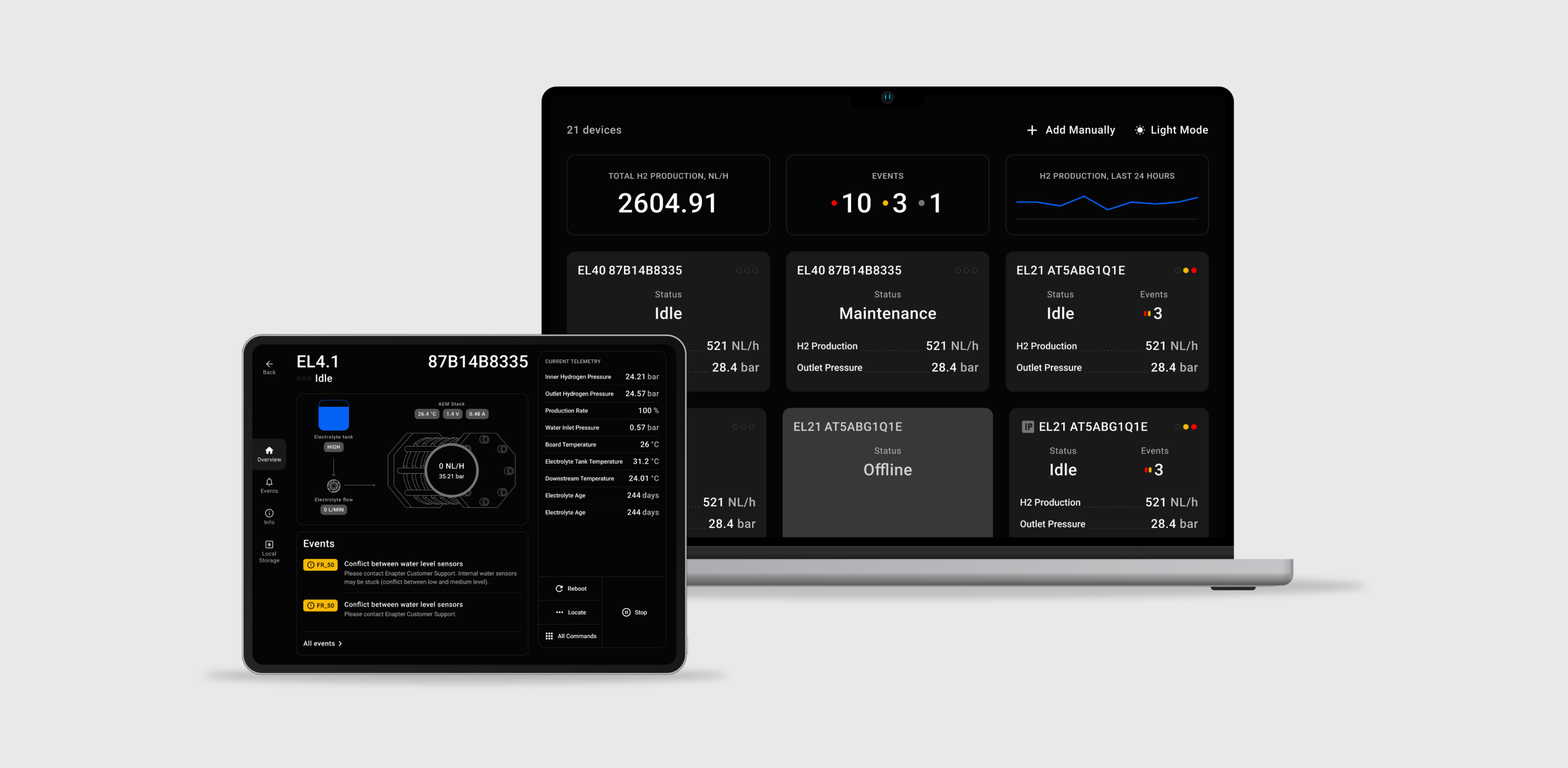
Monitoring and control of Enapter's AEM Electrolysers connected to the local area network.
- Autodetect devices in local area network.
- No internet connection or a Cloud account needed for operation.
- Support unlimited number of electrolysers.
# 🚀 Getting Started
# Connecting
Note
Multicast must be enabled for automatic discovery of devices.
Note
Supported versions of Electrolysers:
- EL 4.1 with firmware version 3.4.0 or later.
- EL 4.0 with firmware version 3.1.0 or later.
- EL 2.1 with firmware version 1.10.0 or later.
Warning
- Multicast and Broadcast must be enabled in the local area network.
- Clients should not be isolated.
- If you have any restrictions, you can use Add Device Manually.
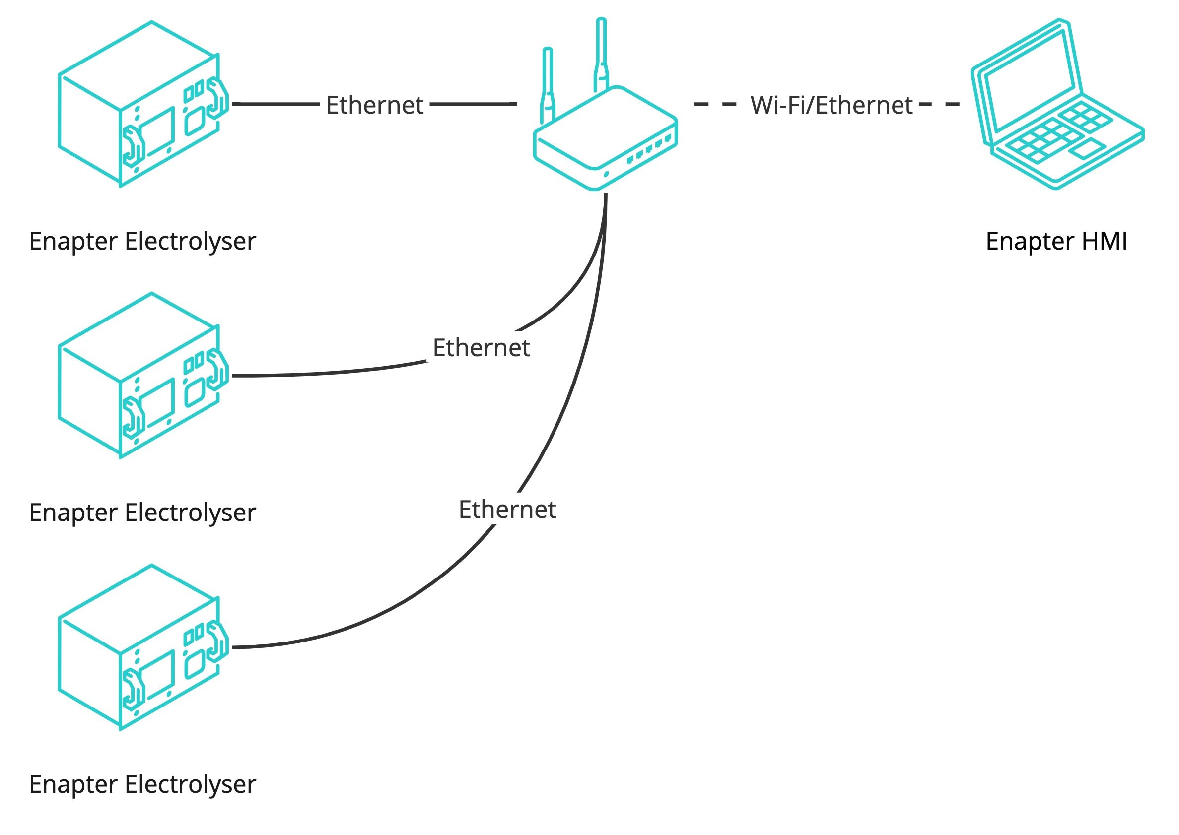
- Connect your electrolysers to the local area network using a cable.
- Download and install Enapter HMI app for Android, MacOS, Windows or Linux from http://hmi.enapter.com/ (opens new window).
- Ensure your computer or android device connected to the same network as electrolysers.
- Open Enapter HMI app on the Android tablet or laptop.
# Connection Example
# Add Device Manually
If the device autodetect does not work you can add electrolysers manually. In order to add the device manually you need to know the IP address of each device.
- Press the
+ Add devicebutton located on the top right corner of the screen.
Add Device Manuallyoverlay will appear.- Enter IP address of the electrolyser.
- Press the
Connectbutton.
# 🔧 Features
- Data stored locally and might be exported as CSV-file.
- Manual connection of electrolysers using IP address.
- All data needed for normal operations and extended telemetry for maintenance or support.
Note
If you want to refill several electrolysers it is recommended to use Enapter HMI (opens new window).
# Service Partner Access
With Service Partner Access you will have access to the extended telemetry set for electrolysers connected to the Enapter HMI.
Note
Your Enapter Cloud account must belong to a certified partner. For more information please contact support@enapter.com.
This documentation provides a step-by-step guide on how to request and activate Service Partner Access for your user account.
- Navigate to the
Settingsin Enapter HMI. - In the
Settingsmenu, locate the option to request Service Partner Access. This option is can be found under the account access section. - Once you've requested
Service Partner Access, you will be presented with aConfirmation Phrase. Make sure to copy or carefully rewrite thisConfirmation Phraseas you will need it for the next steps. - Open your web browser and navigate to https://cloud.enapter.com/hmi-activate (opens new window).
- On the activation website, you will be prompted to insert the
Confirmation Phraseyou obtained earlier. Paste or manually enter theConfirmation Phraseinto the designated field. - After entering the
Confirmation Phrase, click theGenerate Activation Codebutton. This will produce an activation code needed for the next step. - Access the Enapter HMI (Human-Machine Interface) where you will be prompted to enter the generated
Activation Code. Type in theActivation Codeexactly as it appears. - Finally, click the
Applybutton within the Enapter HMI to complete the activation process.
# Electrolyser Metrics CSV Export
Electrolyser metrics can be exported to a .CSV file. This feature allows detailed data analysis and reporting for better system performance. The table below describes the parameters included in the .CSV file, providing insights into each specific metric.
Show more
| Parameter in .CSV file | Description |
|---|---|
| status | Device Status |
| lifetime | Total Lifetime, seconds |
| uptime | Time since last reboot, seconds |
| log_loss | Quantity of lost (discarded) log packets |
| ucm_loss | Quantity of lost (discarded) communication packets |
| storage_free | Free Storage Space, bytes |
| system_free | Unallocated Free Memory, bytes |
| heap_free | Total Free Memory, bytes |
| locate | Locate Mode |
| readonly | Read-Only Mode |
| eth_ip | Ethernet IP Address |
| system | System State |
| electrolyser | Electrolyser State |
| waterrefilling | Water Refilling State |
| service | Service State |
| heartbeat | Heartbeat State |
| hvac | Heating, ventilation, and air conditioning (HVAC) subsystem state |
| recombiner | Recombiner State |
| stack | Stack State |
| curve | Polarization Curve State |
| ui_state | Frontend UI State |
| h2_total | Total Produced Hydrogen, NL |
| h2_flow | Hydrogen Flow, NL/hour |
| production_rate | Hydrogen Production Rate, % |
| stack_runtime | Stack Runtime, seconds |
| stack_cycles | Stack Cycles |
| F103A_out_power | Electrolyte Cooler Fan Powered |
| F103A_in_rpm | Electrolyte Cooler Fan Speed, rpm |
| F103A_out_pwm | Electrolyte Cooler Fan Control Signal, % |
| F104B_in_rpm | Air Circulation Fan Speed, rpm |
| F108C_in_rpm | Electronic Compartment Cooling Fan Speed, rpm |
| F108C_out_pwm | Electronic Compartment Cooling Fan Control Signal, % |
| FM106_in_lmin | Electrolyte Flow Meter, L/min |
| P107_out_power | Electrolyte Pump Powered |
| P107_out_v | Electrolyte Pump Control Signal, V |
| HASS_in_a | Stack Current, amperes |
| HASS_in_v | Stack Current Raw Signal, V |
| PSU_out_power | PSU Powered |
| PSU_in_v | Stack Voltage, V |
| PSU_out_v | PSU Control Voltage, V |
| PT101A_in_bar | Stack Pressure, barg |
| PT101A_in_v | Stack Pressure Raw Signal, V |
| PT101C_in_v | Outlet Pressure Raw Signal, V |
| PT101C_in_bar | Outlet Pressure, barg |
| PT105_in_bar | Water Inlet Pressure, barg |
| TT102A_in_c | Electrolyte Temperature, °C |
| H102_out_power | Electrolyte Heater Power |
| TT106_in_c | Downstream Temperature, °C |
| H109_out_power | Recombiner Heater Power |
| TE109_in_c | Recombiner Temperature, °C |
| HT104_in_ppm | Hydrogen Sensor, ppm |
| HT104_in_v | Hydrogen Sensor Raw Signal, V |
| V5_in_v | +5V Board Voltage, V |
| V12_in_v | +12V Board Voltage, V |
| V24_in_v | +24V Board Voltage, V |
| BAT_in_v | Board Battery Voltage, V |
| MCU_in_c | MCU Temperature, °C |
| BOARD_in_c | Board Temperature, °C |
| TE108_in_c | Safety Board Temperature, °C |
| WLC1_in | Water Level Capacitive Sensor, % |
| LSHH102A_in | Very High Electrolyte Level Reached |
| LSH102B_in | High Electrolyte Level Reached |
| LSM102C_in | Medium Electrolyte Level Reached |
| LSL102D_in | Low Electrolyte Level Reached |
| PSH102_in | Electrolyte Tank High Pressure |
| PSHH101B_in | Very High Hydrogen Pressure |
| TSH106_in | Downstream High Temperature Switch |
| TSH108_in | Electronic Compartment High Temperature Switch |
| TSLL102B_in | Very Low Electrolyte Temperature Switch |
| V101_out_open | Purge Line Solenoid Valve Opened |
| V105_out_open | Water Refilling Solenoid Valve Opened |
| WPS104_in | Chassis Water Presence |
| V106_out_open | Electrolyte Cooler Valve Opened |
| DRYCONTACT_in | Dry Contact Triggered |
| electrolyte_replacement_time | Last Electrolyte Replacement, timestamp |
| depressurization_slope_difference | Stack RampUp Check Difference, barg/s |
| pressurization_slope | Stack Purge Check up Slope, barg/s |
| pressurization_slope_ratio | Stack Purge Check-up Ratio |
| psu_temperature | PSU Temperature, °C |
| psu_air_temperature | PSU Air Temperature, °C |
| psu_board_current | Board Current, amperes |
| psu_board_voltage | Board Voltage, V |
| SB_RELAY_STATUS_in_open | Safety Board Relay Status |
| SB_DRYCONTACT_in_open | Safety Board Dry Contact Open |
| SB_FANDIAG_out_activated | Safety Board Fan Diagnostic Activated |
| SB_WRITE_EN_in_enabled | Safety Board Write Enabled |
| SB_WPSDIAG_out_activated | Safety Board Water Purification System Diagnostic Activated |
| SB_RELAY0_out_open | Safety Board Relay Open |
| SB_PSU_EN_out_power | Safety Board PSU Power Allowed |
| SB_last_code | Safety Board Most Important Current Error Code |
# Overview Video
Was this page useful?


