# EL 2.1 FW 1.2.0 Modbus TCP Communication Interface
# Introduction
Refer to the Reference section for details of the Modbus protocol.
This document describes public Modbus TCP implementation for Enapter Electrolyser EL 2.1 and assume understanding of TCP/IP and Modbus protocols.
# Physical Interface Connection
Connect Ethernet cable to the Ethernet Port of Enapter EL 2.1 electrolyser.
# TCP/IP Connection Settings
By default DHCP client is enabled therefore IP address will be assigned automatically by DHCP server available in the connected network.
It is recommended to set DHCP reservation based on MAC address of the electrolyser.
Configuration of the Static IP is possible using Enapter Cloud and Enapter Mobile Application for iOS and Android.
# Modbus Connection Settings
| Option | Value | Comment |
|---|---|---|
| Modbus Port | 502 | |
| Modbus Slave Address | 1 | Enapter Electrolyser always addressed as a slave |
# References
http://www.modbus.org/docs/Modbus_Application_Protocol_V1_1b.pdf (opens new window)
# Data Formats Used
| Primary tables | Object Type | Permission | Comment |
|---|---|---|---|
| Input Registers | 16 bit word | Read Only | |
| Holding Registers | 16 bit word | Read / Write |
# Data Bits/Registers Dimension
| Data Type | Size in Bits | Registers Used | Comment |
|---|---|---|---|
| Boolean | 16 bits | 1 register | 0 value means 'false', all other cases - 'true' |
| Uint16 | 16 bits | 1 register | |
| Uint32 | 32 bits | 2 registers | |
| Uint64 | 64 bits | 4 registers | |
| Float32 | 32 bits: * bit 31: Sign (1 bit) * bit 30-23: Exponent (8 bits) * bit 22-0: Fraction (23 bits) | 2 registers | IEEE 754 Single-precision loating-point |
# Data Encoding
Big-endian, high word first data encoding used.
This means that when more than single byte (8 bits) is transmitted, network byte order is used - the most significant byte placed at lower address (sent first).
# Implemented Modbus Functions
| Function | Code | Comment |
|---|---|---|
| Read Holding Registers | 03 | |
| Read Input Registers | 04 | |
| Write Single Holding Register | 06 | |
| Write Multiple Holding Registers | 16 |
# Modbus Data Model
Input registers and Holding registers are referred to in the range 3XXXX and 4XXXX respectful (also known as PLC Address). For example, Holding register 0 in this document would be referred to as 40001 and would be addressed as register 0000 in the data address field of the Modbus message (also known as Protocol Address).
# Events
# Severity Levels
| Code | Severity Level | LED Indication | Description | Comment |
|---|---|---|---|---|
| F | Fatal Error | Red and Yellow Blinks | System stopped. Unrecoverable error. Hardware repair required. | e.g. Pressure sensor is not connected or broken. |
| E | Error | Red Blinks | System Stopped. Recoverable error. | e.g. No input water pressure and internal water tank is empty. |
| W | Warning | Yellow Blinks | Heads-up event which should be taken into account to avoid Error or Fatal Error. | e.g. No input water pressure and internal water tank is full. |
# Routines
| Code | Routine | Comment |
|---|---|---|
| P | Platform | |
| C | Electrolyte Circulation | |
| D | Stack Ramp Down | |
| R | Water Refilling | |
| S | Steady Hydrogen Production | |
| T | Temperature Management | |
| U | Stack Ramp Up | |
| X | Safety Check | |
| F | Anti-freezing | |
| L | Leakage Test | |
| O | Blowdown | |
| H | Heartbeat |
# Error Codes
| Error Code | Error Name | Severity Code | Routine Code | Component | Condition | Description |
|---|---|---|---|---|---|---|
| 0x0000 | none | -- | -- | -- | No error | |
| 0x0FFF | int | -- | -- | -- | Unexpected error, hardware failure, read logs for details | |
| 0x1F81 | FP_01 | F | P | -- | Voltage < 2.9V | Brownout detected, restore power and reset system |
| 0x1F82 | FP_02 | F | P | -- | Updated firmware have new mandatory settings | New parameters has been added to configuration, please re-check and write new one, contact enapter support or certified partner |
| 0x108A | FC_10 | F | C | P107 | Pump broken | |
| 0x1114 | FD_20 | F | D | PT101A | Pressure drop > 2% | Hydrogen leaks |
| 0x2DA2 | WR_10 | W | R | PT105 | Pressure > 5barg | Water inlet pressure too high |
| 0x2DAC | WR_20 | W | R | PT105 | Pressure < 0.5barg | Water inlet pressure too low |
| 0x118A | FR_10 | F | R | LSHH102A | Water level over level switch | Electrolyte level too much high |
| 0x1194 | FR_20 | F | R | LSL102D | Water level below level switch | Electrolyte level too much low |
| 0x11B2 | FR_50 | F | R | LSL102D LSM102C | Conflict between water sensors (low and medium level) | |
| 0x11B3 | FR_51 | F | R | LSM102C LSH102B | Conflict between water sensors (medium and high level) | |
| 0x11B4 | FR_52 | F | R | LSH102B LSHH102A | Conflict between water sensors (high and very high level) | |
| 0x11A8 | FR_40 | F | R | -- | Check water leaks | |
| 0x2DAD | WR_21 | W | R | -- | Refilling timeout | |
| 0x2DCB | WR_51 | W | R | LSL102D | Drain completely | |
| 0x2DCC | WR_52 | W | R | LSL102D | Refill to high level | |
| 0x2E2C | WS_20 | W | S | PT101C | Pressure > Max Tank Pressure | Max pressure state |
| 0x2E2D | WS_21 | W | S | PT101A | Pressure spike > 2% | Drifting PT101A |
| 0x128A | FT_10 | F | T | TT106 | Temperature > 58°C | Electrolyte temperature too high |
| 0x3294 | WT_20 | W | T | F103A | Rotation < 600rpm | Electrolyte cooling fan broken |
| 0x228A | ET_10 | E | T | TT102A | Temperature < 6°C | Electrolyte temperature too low |
| 0x2F22 | WU_10 | W | U | PT101A | Pressure is > atmospheric pressure + 10% | Gas side pressure is not atmospheric. Ramp-Up is not possible (pressure too high for start) |
| 0x1401 | FX_01 | F | X | PT101A | Pressure > 37bar | Hydrogen inner pressure too high |
| 0x1402 | FX_02 | F | X | WPS104 | Water sensor is wet | Water presence |
| 0x1403 | FX_03 | F | X | PSU 48V | No voltage from PSU | PSU broken |
| 0x1404 | FX_04 | F | X | HASS | Current > 58A | Stack current too high |
| 0x1405 | FX_05 | F | X | TSH106 | Backflow temperature too high | |
| 0x1406 | FX_06 | F | X | PT101A | Hydrogen leaks | |
| 0x1407 | FX_07 | F | X | TS108 | Temperature > 75°C | Electronic board temperature too high |
| 0x1408 | FX_08 | F | X | PSH102 | Electrolyte tank pressure too high | |
| 0x1409 | FX_09 | F | X | TSLL102B | Electrolyte temperature too low | |
| 0x140A | FX_10 | F | X | PSHH101B | Hydrogen pressure too high | |
| 0x141E | FX_30 | F | X | PT105 | Water inlet pressure transmitter broken | |
| 0x141F | FX_31 | F | X | TT102A | Electrolyte tank temperature transmitter broken | |
| 0x1420 | FX_32 | F | X | FM106 | Electrolyte flow meter broken | |
| 0x1421 | FX_33 | F | X | TT106 | Electrolyte backflow temperature transmitter broken | |
| 0x1422 | FX_34 | F | X | PT101A | Hydrogen inner pressure transmitter broken | |
| 0x1423 | FX_35 | F | X | PT101C | Outer hydrogen pressure transmitter broken | |
| 0x1424 | FX_36 | F | X | F1084B | Rotation < 3000rpm | Chassis circulation fan broken |
| 0x1425 | FX_37 | F | X | F108C | Rotation < 3000rpm | Electronic compartment cooling fan broken |
| 0x1426 | FX_38 | F | X | TS108 | Electronic board temperature transmitter broken | |
| 0x1427 | FX_39 | F | X | HASS | Current sensor broken | |
| 0x1428 | FX_40 | F | X | External switch | Dry contact error | |
| 0x148A | FF_10 | F | F | -- | Frozen pipes | |
| 0x1501 | FL_01 | F | L | -- | Huge H2 leak detected | |
| 0x358A | WO_10 | W | O | PT101C | Pressure > 25 barg | Outer pressure is too high to run blowdown routine |
| 0x3594 | WO_20 | W | O | -- | The Blowdown procedure will be started at H2-production start | |
| 0x159E | FO_30 | F | O | PT101C | The purge line is obstructed or the adjustable check valve (CV101B) cracking pressure is set incorrectly | |
| 0x360A | WH_10 | W | H | ModBus | Heartbeat Packet was not received in time | Lost ModBus safety heartbeat communication |
| 0x360B | WH_11 | W | H | Gateway | Heartbeat Packet was not received in time | Lost Gateway safety heartbeat communication |
| 0x360C | WH_12 | W | H | UCM | Heartbeat Packet was not received in time | Lost UCM safety heartbeat communication |
# Modbus Table
# Holding Registers (Read / Write)
| Register | Data Type | Name | Comment |
|---|---|---|---|
| 0 | Uint64 | Unix Time | Seconds from 1 January 1970 UTC. e.g. 02/29/2020 @ 3:15 PM (UTC) represented as 1582989315. |
| 4 | Boolean | Reboot | 1 = Reboot. |
| 5 | Boolean | Locate Electrolyser | 1 = Start Blinking All LED; 0 = Stop Blinking All LED. |
| 6 | Boolean | Maintenance Mode | 1 = Enable Maintenance Mode; 0 = Disable Maintenance Mode. |
| 1000 | Boolean | Start / Stop Electrolyser | 1 = Start; 0 = Stop. |
| 1002 | Float32 | Production Rate [%] | Current production rate in percent (system reset set this value to 'Default Production Rate'), can be changed 'on-fly' even when electrolyser produce H2 |
| 1010 | Boolean | Request Blowdown routine | 1 = Request blowdown or read 'is blowdown requested' |
| 4000 | Boolean | Configuration Begin | 1 = Start configuration |
| 4001 | Boolean | Configuration Commit | 1 = Commit current changes; 0 = Rollback changes |
| 4020 | Uint32 | Ethernet IP Address | e.g. 0xC0A80201 (192.168.2.1); 0 = DHCP enabled |
| 4022 | Uint32 | Ethernet IP Netmask | |
| 4024 | Uint32 | Ethernet Gateway IP Address | |
| 4308 | Float32 | Max Tank Pressure (Outlet) | bar |
| 4310 | Float32 | Restart Pressure (Outlet) | bar |
| 4396 | Float32 | Default Production Rate [%] | This register can be modified only when stack is inactive (Idle or Maintenance mode) |
| 4600 | Uint32 | Heartbeat ModBus Timeout | seconds |
| 4602 | Uint32 | Heartbeat Gateway Timeout | seconds |
| 4604 | Uint32 | Heartbeat UCM Timeout | seconds |
# Input Registers (Read Only)
| Register | Data Type | Name | Comment |
|---|---|---|---|
| 0 | Uint32 | Device Model | 0x454C3231 for EL 2.1 |
| 2 | Uint16 | Firmware MAJOR and MINOR Version | Ex: 267 => 267 // 256 = 1, 267 % 256 => 11 (1.11) |
| 3 | Uint16 | Firmware PATCH Version | Ex: 3 => 3 (3) |
| 4 | Uint32 | Firmware Build Number | e.g. 0x4E343471 |
| 6 | Uint128 | Device Control Board Serial Number | 9E25E695-A66A-61DD-6570-50DB4E73652D |
| 14 | Uint64 | Cabinet (Chassis) Serial Number | 19030125124810 |
| 18 | Uint16 | System State | 0 = Internal Error, System not Initialized yet; 1 = System in Operation; 2 = System Halted (e.g. during error); 3 = System in Maintenance Mode; 4 = Fatal Error; 5 = System in Expert Mode. |
| 20 | Uint32 | Live time [seconds] | Total time during which a system is power up (not only time when stack is working). |
| 22 | Uint32 | Uptime [seconds] | How long the system has been running |
| 768 | Array of 32 Warning Events | Warning Events Array | Warning Events Array represented by Error Codes. First Uint16 contains total quantity of Warning Events. |
| 832 | Array of 32 Error Events | Error Events Array | Error Events Array represented by Error Codes. First Uint16 contains total quantity of Error Events. |
| 1000 | Uint32 | Product Code | 0x00 = ELE210535A2AXV01_03 0x01 = ELE210508A2AXV01_03 |
| 1002 | Uint32 | Stack Start/Stop Cycles Quantity | |
| 1004 | Uint32 | Stack Total Runtime | seconds |
| 1006 | Float32 | Stack Total H2 Production | NL |
| 1008 | Float32 | H2 Flow Rate | NL/hour, NAN when not producing H2; |
| 4000 | Boolean | Configuration Progress | 1 = Configuration is in progress. |
| 4001 | Boolean | Configuration Source | 1 = Configuration over Modbus. |
| 4002 | Int32 | Last Configuration Result | 0 = OK, Configuration was completed successfully; 1 = Permanent, The operation has failed (internal or general error); 2 = No Entry, Configuration was not started or interrupted; 5 = I/O, Data save error; 11 - Try again, Configuration needs to be tried again; 13 = Access Denied, Some changed registers are read-only; 16 = Busy, Another configuration was in progress; 22 = Invalid, The data has invalid or wrong type. |
| 4004 | Uint16 | Last Configuration Wrong Holding | Keeps first invalid Holding register number which doesn't allow successful configuration commit. |
| 4600 | Uint16 | Heartbeat | |
| 7000 | Boolean | High Electrolyte Level Switch (LSH102B_in) | 1 = Electrolyte level over sensor; 0 = Electrolyte level below sensor. |
| 7001 | Boolean | Very High Electrolyte Level Switch (LSHH102A_in) | 1 = Electrolyte level over sensor; 0 = Electrolyte level below sensor. |
| 7002 | Boolean | Low Electrolyte Level Switch (LSL102D_in) | 1 = Electrolyte level over sensor; 0 = Electrolyte level below sensor. |
| 7003 | Boolean | Medium Electrolyte Level Switch (LSM102C_in) | 1 = Electrolyte level over sensor; 0 = Electrolyte level below sensor. |
| 7004 | Boolean | Electrolyte Tank High Pressure Switch (PSH102_in) | 1 = Pressure is too high; 0 = Pressure is normal. |
| 7005 | Boolean | Very High Hydrogen Pressure Switch (PSHH101B_in) | 1 = Pressure is too high; 0 = Pressure is normal. |
| 7006 | Boolean | Downstream High Temperature Switch (TSH106_in) | 1 = Temperature is too high. 0 = Temperature is normal. |
| 7007 | Boolean | Electronic Compartment High Temperature Switch (TSH108_in) | 1 = Temperature is too high. 0 = Temperature is normal. |
| 7008 | Boolean | Very Low Electrolyte Temperature Switch (TSLL102B_in) | 1 = Temperature is too low. 0 = Temperature is normal. |
| 7009 | Boolean | Chassis Water Presence Switch (WPS104_in) | 1 = Water is present on input; 0 = No water input. |
| 7500 | Float32 | Electrolyte Cooler Fan Speed (F103A_in_rpm) | [rpm] |
| 7502 | Float32 | Air Circulation Fan Speed (F104B_in_rpm) | [rpm] |
| 7504 | Float32 | Electronic Compartment Cooling Fan Speed (F108C_in_rpm) | [rpm] |
| 7506 | Float32 | Electrolyte Flow Meter (FM106_in_lmin) | [Liters per minute] |
| 7508 | Float32 | Stack Current (HASS_in_a) | [Ampere] |
| 7510 | Float32 | PSU Voltage Signal (PSU_in_v) | [Volt] |
| 7512 | Float32 | Inner Hydrogen Pressure (PT101A_in_bar) | [bar] |
| 7514 | Float32 | Outer Hydrogen Pressure (PT101C_in_bar) | [bar] |
| 7516 | Float32 | Water Inlet Pressure (PT105_in_bar) | [bar] |
| 7518 | Float32 | Electrolyte Temperature (TT102A_in_c) | [°C] |
| 7520 | Float32 | Downstream Temperature (TT106_in_c) | [°C] |
| 8000 | Float32 | Inner Hydrogen Pressure Raw Sensor Value (PT101A_in_v) | Raw value, [Volt] |
| 8002 | Float32 | Outer Hydrogen Pressure Raw Sensor Value (PT101C_in_v) | Raw value, [Volt] |
| 8004 | Float32 | Stack Current Raw Sensor Value (HASS_in_v) | Raw value, [Volt] |
# Diagrams
# System State Diagram
This diagram describes possible transition between different electrolyser states. The state can be read in the Input Register #18.
# Examples
# Example: Change Electrolyser Restart Pressure Flow
Here is an example to change Electrolyser Restart Pressure to 25 bar. This will enable Electrolyser to restart when pressure drop to 25 bar on outlet.
# Example: Reading Modbus Input Registers
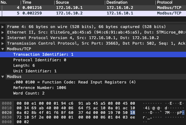
Request Packet
Transaction ID Protocol ID Query Length Unit ID Function Code Reference Number Word Count 00 01 00 00 00 06 01 04 03 EE 00 02 Request Packet Description
Modbus/TCP
- Transaction ID – default: 00 01
- Protocol ID – default: 00 00
- Query Length – default: 00 06
- Unit ID: Slave Address – default: 01
Modbus
- Function Code: Read Input Registers – default: 04
- Reference Number: Starting register – decimal: 1006
- Word Count: Number of registers to read – decimal: 2
Wireshark Example
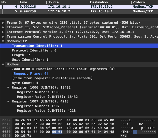
Response Packet
Transaction ID Protocol ID Query Length Unit ID Function Code Byte Count Register[0] Register[1] 00 01 00 00 00 07 01 04 04 48 00 10 7A Response Packet Description
Modbus/TCP
- Transaction ID – default: 00 01
- Protocol ID – default: 00 00
- Query Length – decimal: 7
- Unit ID: Slave Address – default: 01
Modbus
- Function Code: Read Input Registers – default: 04
- Byte Count: Registers values size – decimal: 4
- Register[0] value – decimal: 18432
- Register[1] value – decimal: 4218
- Register[…] value – 2 bytes
Wireshark Example
# Example: Writing to Modbus Holding Registers
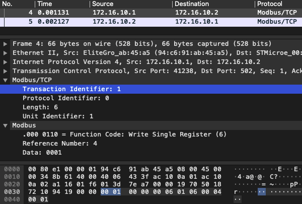
Request Packet
Transaction ID Protocol ID Query Length Unit ID Function Code Reference Number Data 00 01 00 00 00 06 01 06 00 04 00 01 Request Packet Description
Modbus/TCP
- Transaction ID – default: 00 01
- Protocol ID – default: 00 00
- Query Length – default: 00 06
- Unit ID: Slave Address – default: 01
Modbus
- Function Code: Write Single Register – default: 06
- Reference Number: Starting register – decimal: 4
- Data: Value to write – decimal: 1
Wireshark Example
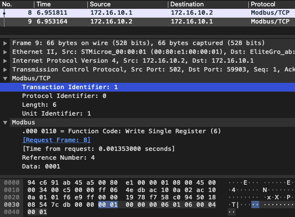
Response Packet
Transaction ID Protocol ID Query Length Unit ID Function Code Reference Number Data 00 01 00 00 00 06 01 06 00 04 01 Response Packet Description
Modbus/TCP
- Transaction ID – default: 00 01
- Protocol ID – default: 00 00
- Query Length – default: 00 06
- Unit ID: Slave Address – default: 01
Modbus
- Function Code: Write Single Register – default: 06
- Reference Number: Register to write – decimal: 4
- Data: Value to write – decimal: 1
Wireshark Example
# Example: Reading Errors Sequence
Request Packet
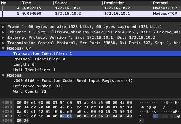
Transaction ID Protocol ID Query Length Unit ID Function Code Reference Number Word Count 00 01 00 00 00 06 01 04 03 40 00 20 Request packet description
Modbus/TCP
- Transaction ID – default: 00 01
- Protocol Identifier – default: 00 00
- Query Length – default: 00 06
- Unit ID: Slave Address – default: 01
Modbus
- Function Code: Read Input Registers – default: 04
- Reference Number: Starting register – default: 03 40
- Word Count: Number of registers to read – default: 00 20
Wireshark Example
Response Packet
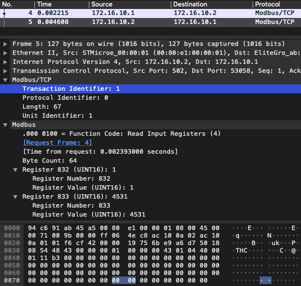
Transaction ID Protocol ID Query Length Unit ID Function Code Byte Count Register[0] Register[1] 00 01 00 00 00 43 01 04 40 00 01 11 B3 Response packet description
Modbus/TCP
- Transaction ID – default: 00 01
- Protocol ID – default: 00 00
- Query Length – default: 00 43
- Unit ID: Slave Address – default: 01
Modbus
- Function Code: Read Input Registers – default: 04
- Byte count: Registers values size – default: 40
- Register[0] value – total number of errors, decimal: 1
- Register[1] value – error code 1: 11 B3
- Register[…] value – error code N
Wireshark Example
# Example: Writing Heartbeat Modbus Timeout
Request Packet
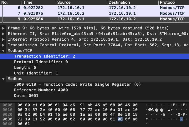
Transaction ID Protocol ID Query Length Unit ID Function Code Reference Number Data 00 02 00 00 00 06 01 06 0F A0 00 01 Request Packet Description
Modbus/TCP
- Transaction ID – decimal: 2
- Protocol ID – default: 00 00
- Query Length – default: 00 06
- Unit ID: Slave Address – default: 01
Modbus
- Function Code: Write Single Register – default: 06
- Reference Number: Starting register – decimal: 4000
- Data: Value to write – decimal: 1
Wireshark Example
Response Packet
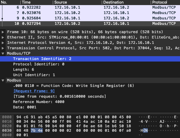
Transaction ID Protocol ID Query Length Unit ID Function Code Reference Number Data 00 02 00 00 00 06 01 06 0F A0 00 01 Response Packet Description
Modbus/TCP
- Transaction ID – decimal: 2
- Protocol ID – default: 00 00
- Query Length – default: 00 06
- Unit ID: Slave Address – default: 01
Modbus
- Function Code: Write Single Register – default: 06
- Reference Number: Register to write – decimal: 4000
- Data: Value to write – decimal: 1
Wireshark Example
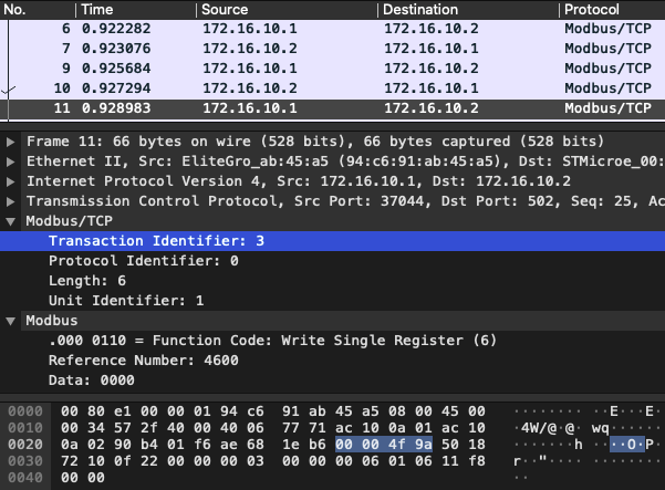
Request Packet
Transaction ID Protocol ID Query Length Unit ID Function Code Reference Number Data 00 03 00 00 00 06 01 06 11 F8 00 00 Request Packet Description
Modbus/TCP
- Transaction ID – decimal: 3
- Protocol ID – default: 00 00
- Query Length – default: 00 06
- Unit ID: Slave Address – default: 01
Modbus
- Function Code: Write Single Register – default: 06
- Reference Number: Starting register – decimal: 4600
- Data: Value to write – decimal: 0
Wireshark Example
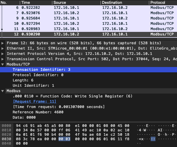
Response Packet
Transaction ID Protocol ID Query Length Unit ID Function Code Reference Number Data 00 03 00 00 00 06 01 06 11 F8 00 00 Response Packet Description
Modbus/TCP
- Transaction ID – decimal: 3
- Protocol ID – default: 00 00
- Query Length – default: 00 06
- Unit ID: Slave Address – default: 01
Modbus
- Function Code: Write Single Register – default: 06
- Reference Number: Register to write – decimal: 4600
- Data: Value to write – decimal: 0
Wireshark Example
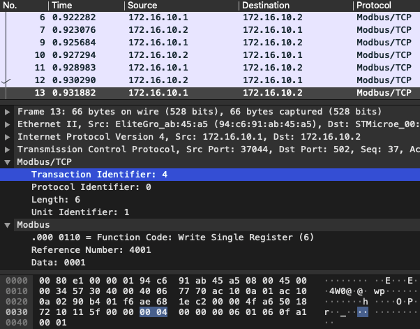
Request Packet
Transaction ID Protocol ID Query Length Unit ID Function Code Reference Number Data 00 04 00 00 00 06 01 06 0F A1 00 01 Request Packet Description
Modbus/TCP
- Transaction ID – decimal: 4
- Protocol ID – default: 00 00
- Query Length – default: 00 06
- Unit ID: Slave Address – default: 01
Modbus
- Function Code: Write Single Register – default: 06
- Reference Number: Starting register – decimal: 4001
- Data: Value to write – decimal: 1
Wireshark Example
Response Packet
Transaction ID Protocol ID Query Length Unit ID Function Code Reference Number Data 00 04 00 00 00 06 01 06 0F A1 00 01 Response Packet Description
Modbus/TCP
- Transaction ID – decimal: 4
- Protocol ID – default: 00 00
- Query Length – default: 00 06
- Unit ID: Slave Address – default: 01
Modbus
- Function Code: Write Single Register – default: 06
- Reference Number: Register to write – decimal: 4001
- Data: Value to write – decimal: 1
Was this page useful?
