# ENP-RL6 M2
Important Note
ENP-RL6 M2 module is the next-generation replacement for the ENP-RL6 (opens new window).
The first production batch is currently under manufacturing. For pre-order inquiries, please contact your Sales Representative.

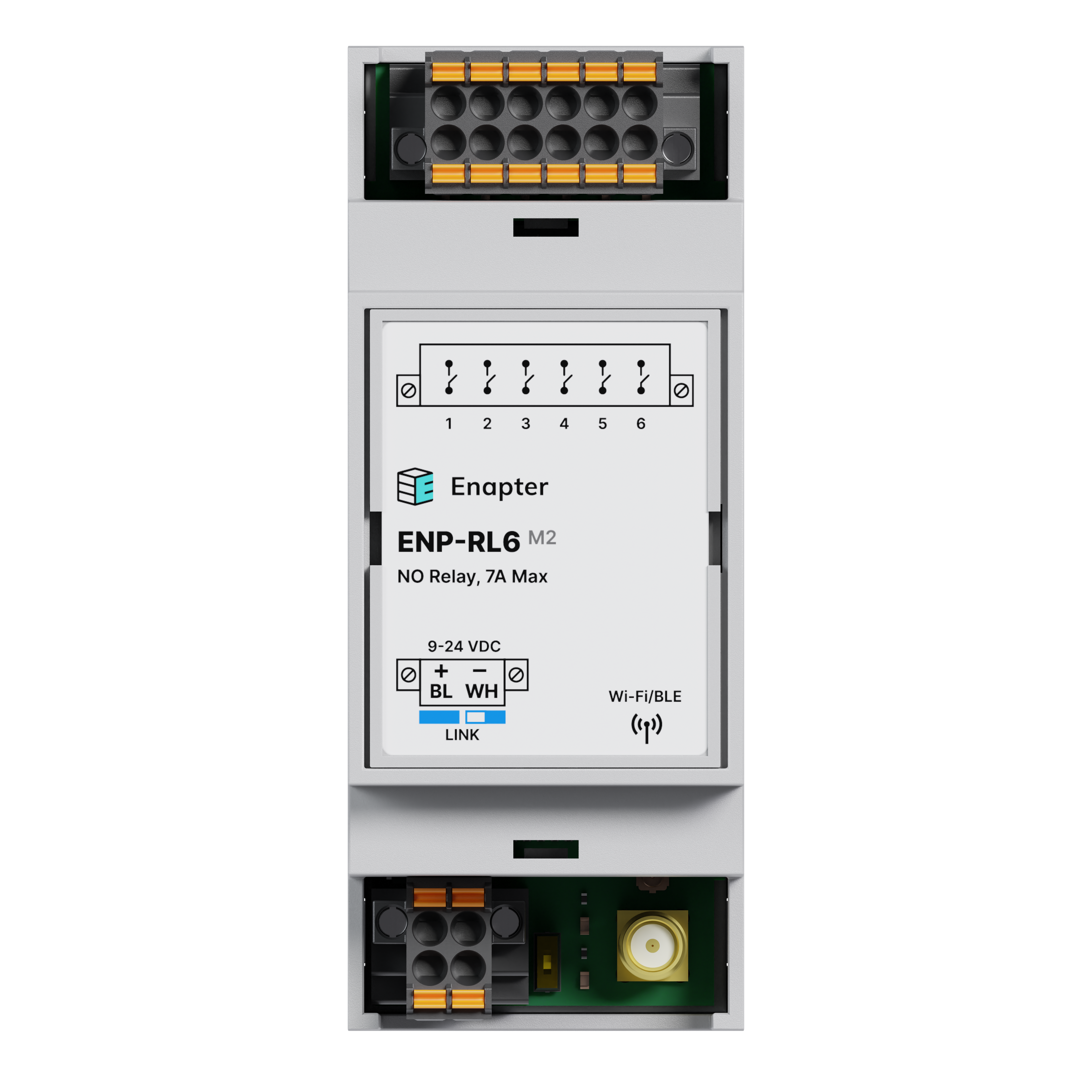
The ENP-RL6 M2 Module features 6 normally open relay outputs. It is used to control low-power load without high inrush currents. For example: a normal closed valve, a normal open valve, signal lamps or intermediate contactors, etc.
The ENP-RL6 M2 Module features a wired bus Enapter Link interface alongside wireless Bluetooth and Wi-Fi capabilities, enabling control and secure data transmission to the Enapter Gateway and Cloud. Additionally, it can communicate with other modules via the wired Enapter Link protocol.
# Resources
| Datasheet | Quick Start Guide | Certification | Images | |
|---|---|---|---|---|
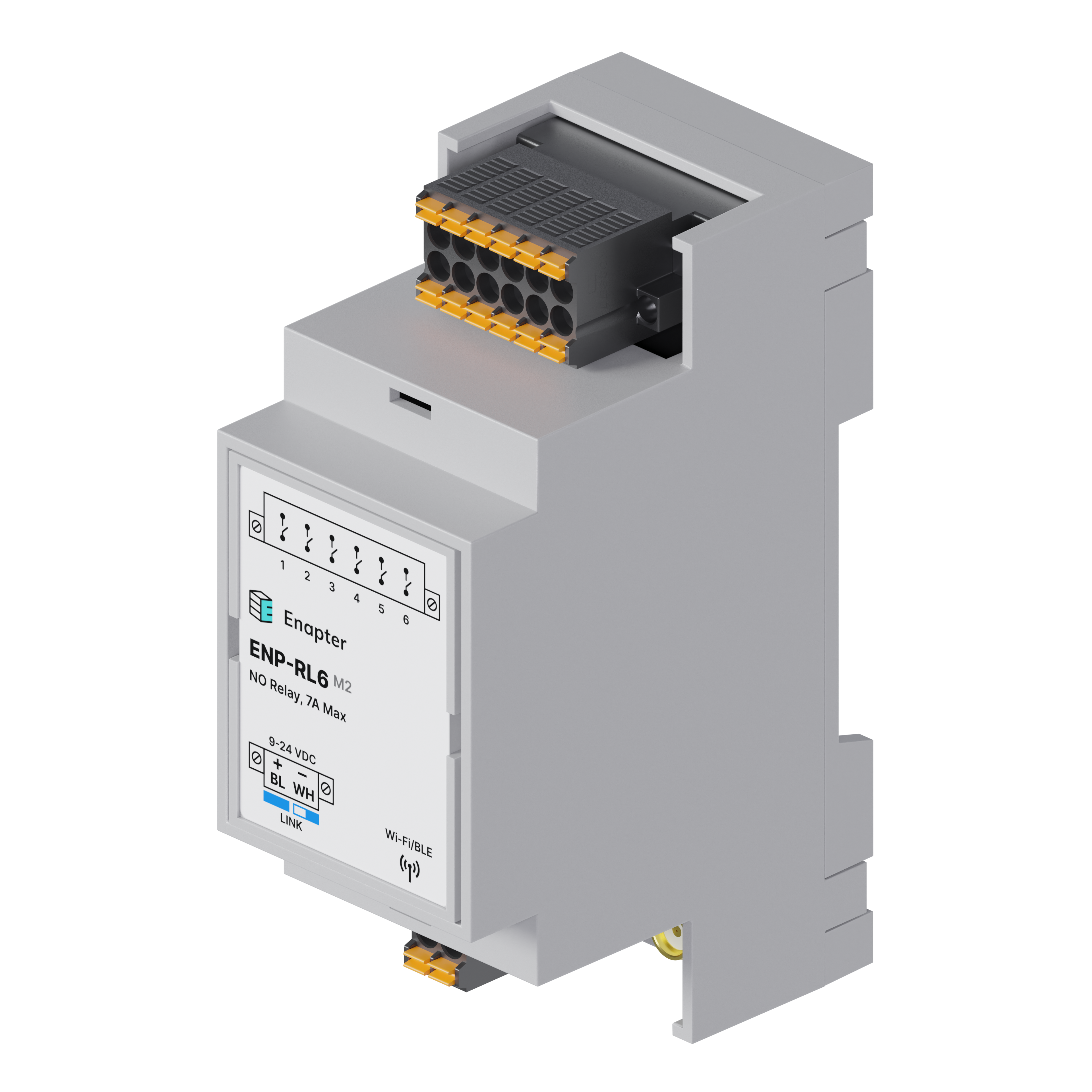
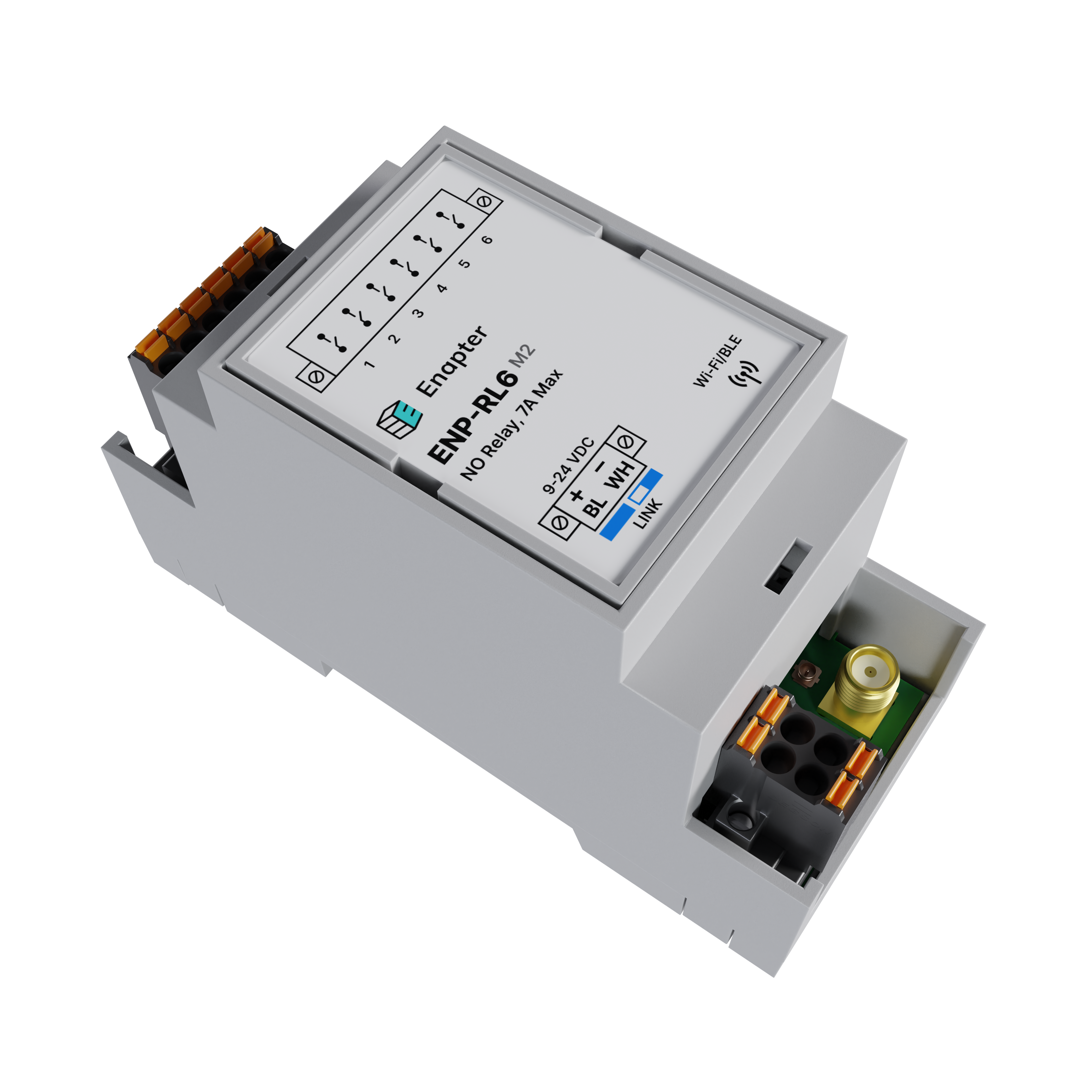
| ENP-RL6 M2 | EN | EN | CE RoHS | Front View Isometric Table View |
Note
The wireless module integrated into this device is certified in accordance with applicable standards. The relevant certificates can be downloaded from the archive.
# Technical Data
| Parameter | Value |
|---|---|
| Power supply | Voltage Range: 9 - 24 VDC |
| Protections: - Reverse polarity protection - Crowbar overvoltage protection (resettable fuse) | |
| Power consumption | Full Load: 6 W, Peak |
| Outputs | Type: 6 Outputs (Relays), Normally Open Maximum Switching Voltage: 250 VAC / 30 VDC Maximum Switching Current per Channel: 7A AC |
| Wireless Communication | Wi-Fi 2.4 GHz, IEEE 802.11b/g/n, 20 MHz/40 MHz bandwidth, data rate up to 150 Mbps Bluetooth v5: Bluetooth LE, Bluetooth mesh, data rate up to 2 Mbps Power: Up to +20 dBm |
| Wired Interface | Protocols Supported: Enapter Link Baud Rate: Up to 0.5 Mbps Isolation: Galvanically isolated from the power supply Internal Bus Terminator*: 120 Ω, enabled via DIP switch (default: off) |
| Local signaling | 1 LED - Status (Green): - Steady: Correct operation - Blinking: Establishing connection with the server (Enapter Gateway or Cloud) |
| 1 LED – Error (Red): -Indication of module error or internal running logic error, can be programmed by the user (see programming manual) | |
| 6 LEDs – Relay Output Status (Green): - Each LED corresponds to a particular channel - Steady: Relay closed | |
| Mounting | 35 mm Din rail acc. to IEC 60715 |
| Height | 90.2 mm (3.55 inch) |
| Depth | 57.5 mm (2.26 inch) |
| Width | 36.3 mm (1.43 inch) |
| Net weight | 0.090 kg |
* – The terminator is a resistor used at the ends of a differential data bus, to reduce signal reflections. The module has a built-in terminator, which can be enabled if the device is positioned at the end of the bus. However, in some cases, even if the device is at the end of the bus, enabling the terminator may degrade or disrupt communication. This depends on various factors, such as baud rate, line length, signal rise time, and the characteristics of connected third-party equipment, which cannot be predicted in advance.
General recommendation: Try enabling the terminator if communication is unstable. For short line lengths (less than one meter) and relatively low baud rates (such as 115200), enabling the terminator is likely unnecessary.
# Environmental Conditions
| Parameter | Value |
|---|---|
| Ambient air temperature for operation | -40 – +60 °C |
| Ambient air temperature for storage | -40 – +60 °C |
| Relative humidity for operation | 20 – 90 %, without condensation |
| Relative humidity for storage | 20 – 90 %, without condensation |
| Operating altitude | 0 – 2000 m |
| Storage altitude | 0 – 3500 m |
| Pollution degree | 2 |
| IP degree of protection | IP20 |
# Connection
| Parameter | Value |
|---|---|
| Wire cross-section | Power Supply / Enapter Link / Relay Connection: Wire Size: 0.14 to 1.5 mm2 / AWG 26 to 16 (use appropriate wire size for the output connected load) Strip Length: 10 mm Temperature resistance: -40 – +105 °C / -40 – +221 °F Push-in connection technology, fast wiring |
| Antenna connection type | SMA-F (module) – SMA-M (antenna), 2.4 GHz |
# Module Overview

# Dimensions
The dimensions are in mm and in brackets in inch.

# Wired Connection Example
Here you can find an example connection, where a lamp is connected to the first channel and a valve to the sixth channel of the module.
The module is connected to the Enapter Link bus alongside other Enapter modules. The Enapter Link bus requires terminators at both ends, which is built into the module and can be enabled via a DIP switch if the module is positioned at the end of the bus. (Note that while separate resistors are shown in the diagram, they should not be used if the internal terminator is enabled.)

# Wireless Connection Example
Here you can find an example of a wireless connection, where the module is connected to the same loads as in the previous example, with a lamp connected to the first channel and a valve to the sixth channel. However, unlike the wired Enapter Link connection, the setup and data exchange occur through a secure Wi-Fi network. For instructions on configuring the wireless connection, please refer to the Quick Start Guide.

# Warnings
WARNING
Alternating current voltage of 110 - 220 V is potentially lethal!
All works on assembly and installation should be performed only with a disconnected power supply!
The installation and assembly of device must be carried out by electrician in accordance with the applicable regulations.
# Safety Instructions
WARNING
This device must be mounted on a DIN rail in an electrical distribution enclosure accordingly with this manual to ensure protection against contact, water and dust.
This device must not be used as part of safety-critical systems.
Edge processing scripting should be used as a convenience feature for basic non-realtime automation and not for life-sustaining or safety-critical use cases. Normal operation depends on working internet, Wi-Fi, and Enapter Cloud. Enapter is not responsible for any harms or losses incurred as a result of any failed automation.
Was this page useful?